5
Caution
If you leave the key in the ignition switch, someone could accidently start the engine and
seriously injure you or other bystanders.
Remove the key from the ignition before installing, servicing, or making adjustments to the
cutting units.
Installing the Tipper Plates and
Weights to the Cutting Units
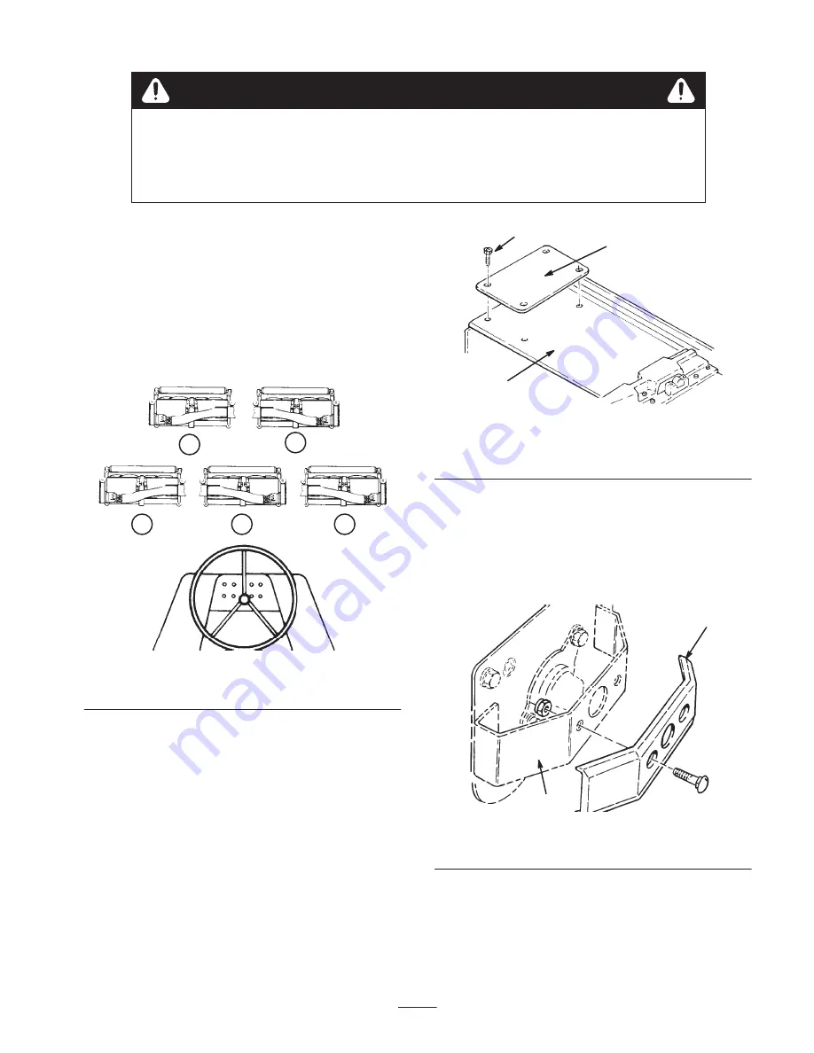
1. Refer to Figure 1 and layout all five cutting units on
the floor in front of the machine. Position 3 right-hand
cutting units (all three are alike) as #1, #3 and #5.
Position the left-hand #2 and #4 cutting units also
(both are alike).
1
2
3
5
4
FRONT
Figure 1
Cutting Unit Layout
2. Install a front roller or skid kit to each cutting unit.
Installation instructions and cutting unit guards are
included with each kit.
3. On the #2 and #3 cutting units, remove 4 cover
capscrews located at the outside end of the cutting unit
drive housing. Discard cover screws. Mount a tipper
plate to front left-hand (#2) cutting unit and the front
right-hand (#3) cutting unit using flathead socket
screws and locknuts supplied with tipper plates
(Fig. 2).
1
2
3
Figure 2
1.
Inboard cutting unit cover
2.
Tipper plate
3.
Flathead socket capscrew
Note: Do not install a tipper plate on the #1 cutting unit.
4. Mount one weight to each cutting unit guard (Fig. 3)
on the #1, #2 and #3 cuttings. Weights are located at
the opposite end of each cutting unit drive housing.
Use 1/2 in. carriage bolts provided with weights
(Fig. 3).
1
2
Figure 3
1.
Weight
2.
Guard
5. On the #4 and #5 cutting units, remove 4 cover
capscrews located at the outside end of the cutting unit
drive housing. Discard cover screws. Tipper brackets
will be mounted at these locations after the #4 and #5
cutting units are mounted on lift arms (Fig. 2).


