


12.03
2
TO.330.
M
.
27
VAD
-
-
-
-
OPERATION AND MAINTENANCE
BETRIEBS- UND WARTUNGSANLEITUNG
UTILISATION ET ENTRETIEN
USO E MANUTENZIONE
ASSEMBLY
MONTAGE
MONTAGE
MONTAGGIO
MIC 23
La confezione comprende:
A ) n° 1 scatola con scheda e mi-
crointerrutori incorporati
B) n° 1 pressacavo
C) n° 1 distanziale (non montare
su CP101 e CP063)
D) n° 2 camme
E) n° 1 coperchio con guarnizio-
ne e viti di fissaggio
F) n° 1 tappo con freccia
G) n° 1 OR
H) n° 3 viti fissaggio MIC ad at-
tuatore
I) n° 3 viti fissaggio coperchio
L) n° 1 boccola in ottone
M) n° 1 rondella dentellata
Lieferumfang beinhalted:
A ) 1 Kunststoffbox mit integrier-
ter Mikroschalterplatine
B) 1 PG-Verschraubung
C) 1 Distanzring (nicht bei CP101
und CP063 verwenden)
D) 2 Schaltnocken
E) 1 Deckel mit Dichtung und Be-
festigungsschrauben
F) 1 Zeigerkappe
G) 1 O-Ring
H) 3 Antriebsbefestigungs-
schrauben
I) 3 Deckelbefestigungs-
schrauben
L) 1 Messingbuchse
M) 1 Fächerscheibe
Supply includes:
A ) 1 microswitch box c/w cir-
cuit board and micro-switch-
es
B) 1 cable gland
C) 1 spacer (do not use for
CP101
and CP063)
D) 2 cams
E) 1 cover with gasket and fix-
ing screws
F) 1 indicator cap
G) 1 O-Ring
H) 3 actuator mounting socket
s c r e w s
I) 3 cover fixing screws
L) 1 brass bushing
M) 1 serrated washer
Le conditionnement
comprend :
A ) 1 boîtier avec carte et micro-
interrupteurs incorporés
B) 1 serre-câble
C) 1 entretoise (ne pas monter
sur CP101 et CP063)
D) 2 cames
E) 1 couvercle avec garniture et
vis de fixation
F) 1 bouchon avec flèche
G) 1 Joint torique
H) 3 vis de fixation MIC à
actionneur
I) 3 vis de fixation du couver-
cle
L) 1 embout en laiton
M) 1 rondelle crantê
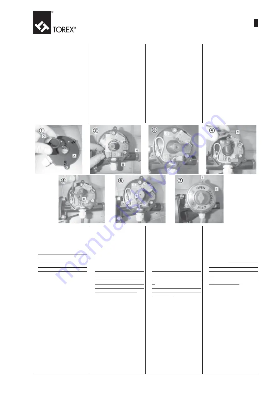
1) Wellenschutz des Antriebs ent-
fernen.
Den O-Ring in seinen Sitz im
unteren Teil der Kunststoffbox
(A) stecken.
2) Die Kunststoffbox (A) positio-
nieren, die Messingbuchse (L)
in ihren Sitz stecken und mit
den 3 Schrauben (H) befesti-
gen.
N.B.: Bevor man die Schrau-
be auf der Buchse (L) befes-
tigt, das gelbgrüne Erdungs-
kabel anschließen und mit der
Scheibe (M) blockieren, die
mit Anzeiger versehen ist. Si-
cherstellen, dass PG-Ver-
schraubung (B) nach unten
zeigt.
3) Kabelanschluss unter Verwen-
dung Kabels laut Schaltplan
auf der Platine im Gehäusein-
nem an der Klemmenleiste
vornehmen.
4) Distanzring (C) bis zum An-
schlag auf den Antriebswellen-
zapfen schieben (nicht bei
CP1 01). Die 2 Schaltnocken
(G) getrennt montieren und
an den Anschlag bringen, wo-
bei darauf zu achten ist, dass
der Schraubenkopf links ange-
ordnet wird, damit genug Platz
zum Ansetzen des Werkzeug-
schlüssels vorhanden ist.
1) Togliere la protezione dal-
l'albero.Inserire l'O-ring (G)
nella parte inferiore della sca-
tola (A) nell'apposita sede.
2) Posizionare la scatola (A) sul-
l'albero dell'attuatore, inseri-
re la boccola in ottone (L) nel-
l'apposita sede, fissare con le
tre viti (H). N.B.: prima di fis-
sare la vite sulla boccola (L)
collegare il cavo giallo-verde
di protezione terra e bloccare
con rondella (M) già fornite
con il segnalatore. Posiziona-
re il pressacavo (B) verso il
basso.
3) Collegare il cavo elettrico ai
morsetti presenti sulla scheda
consultando lo schema di col-
legamento stampato sulla
scheda all'interno della sca-
tola.
4) Inserire il distanziale (C) sul-
l'albero e spingere fino alla
battuta finale (non per il mo-
dello CP 101); inserire quindi
separatamente le due camme
(D) e portarle a battuta, aven-
do cura di collocare la testa
della vite sul lato sinistro, per
ottenere lo spazio di manovra
necessario per la chiave.
1) Remove shaft protection. In-
sert O-ring (G) in the lower part
in the housing in box (A).
2) Place switch box (A), insert
brass bushing (L) in its hous-
ing and fix it with 3 screws (H).
N.B.: before fixing the screw
on bushing (L) connect the yel-
low-green safety earth wire
and lock it using washer (M)
already supplied with marker.
Position cable gland (B) poin-
ting downwards.
3) Connect the cables to termi-
nals on the board according
to wiring diagram printed on
circuit board inside switch box.
4) Push spacer (C) over actuator
shaft as far as it will go (not
with CP101). Now fit the 2
cams (D) flush positioning the
fixing screw head on the left
in such a way that there is
enough room for the spanner.
1) Enlever la protection de l'ar-
bre.
Introduire le joint torique (G)
dans le logement situé dans
la partie inférieure de la boîte
(A).
2) Positionner la boîte (A), intro-
duire l'embout en laiton (L)
dans le logement prévu, fixer
à l'aide des 3 vis (H).
N. B.: avant de fixer la vis sur
l'embout (L), brancher le câ-
ble jaune-vert de protection de
l a
terre et bloquer à l'aide de la
rondelle (M) déjà fournie avec
l'avertisseur. Positionner le
serre-câble (B) vers le bas.
3) Relier le câble électrique aux
bomes présentes sur la carte
en s'aidant du schéma des
connexions imprimé sur la car-
te électronique à l'intérieur du
boîtier.
4) Pousser l'entretoise (C) sur l'ar-
bre jusqu'en butée (pas pour
le modèle CP1 01) ; ensuite,
monter les deux cames (D) sé-
parément en veillant à bien
positionner la tête de la vis
sur la partie gauche afin que
la clé ait suffisamment de pla-
ce pour manœuvrer.


