


- 11 -
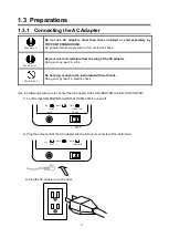
1.3.4 Turning ON/OFF the Power
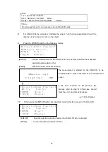
Flip the power switch to the right side to turn on the power.
When the power is turned on, the LCD screen will display an initialization screen, a maintenance
reminder screen and then the most recent measurement data.
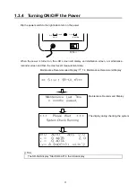
Maintenance Recommended Display
☞
‘1.4 Maintenance Recommend Display’
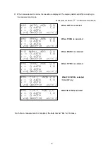
#10
AUTO
ABS
2.0
x
=
0.4476
2
.0
y
=
0.4074
Lv=
8.940E+01
cd/m^2
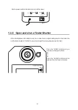
∙ The SR-3AR display “Start SR-3AR” in the initial display
**
Start
SR-UL1R**
Maintenance Recommend Display
Maintenance Last Time
n months passed
.
***
Please Wait
***
System Check Running.
The display during checking the system
ON
→
FUNCTION
SHIFT
LAMP
FIELD
DIF.
DC IN
POWER
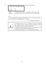
Note
Содержание SR-3AR
Страница 1: ...INSTRUCTION MANUAL SPECTRORADIOMETER Rev 20...
Страница 2: ......
Страница 104: ...93...


