Setup V
e
rification
Testing Machine Element Sensors for Accuracy
61
Excavator Indicate System
P/N: 1022461-01
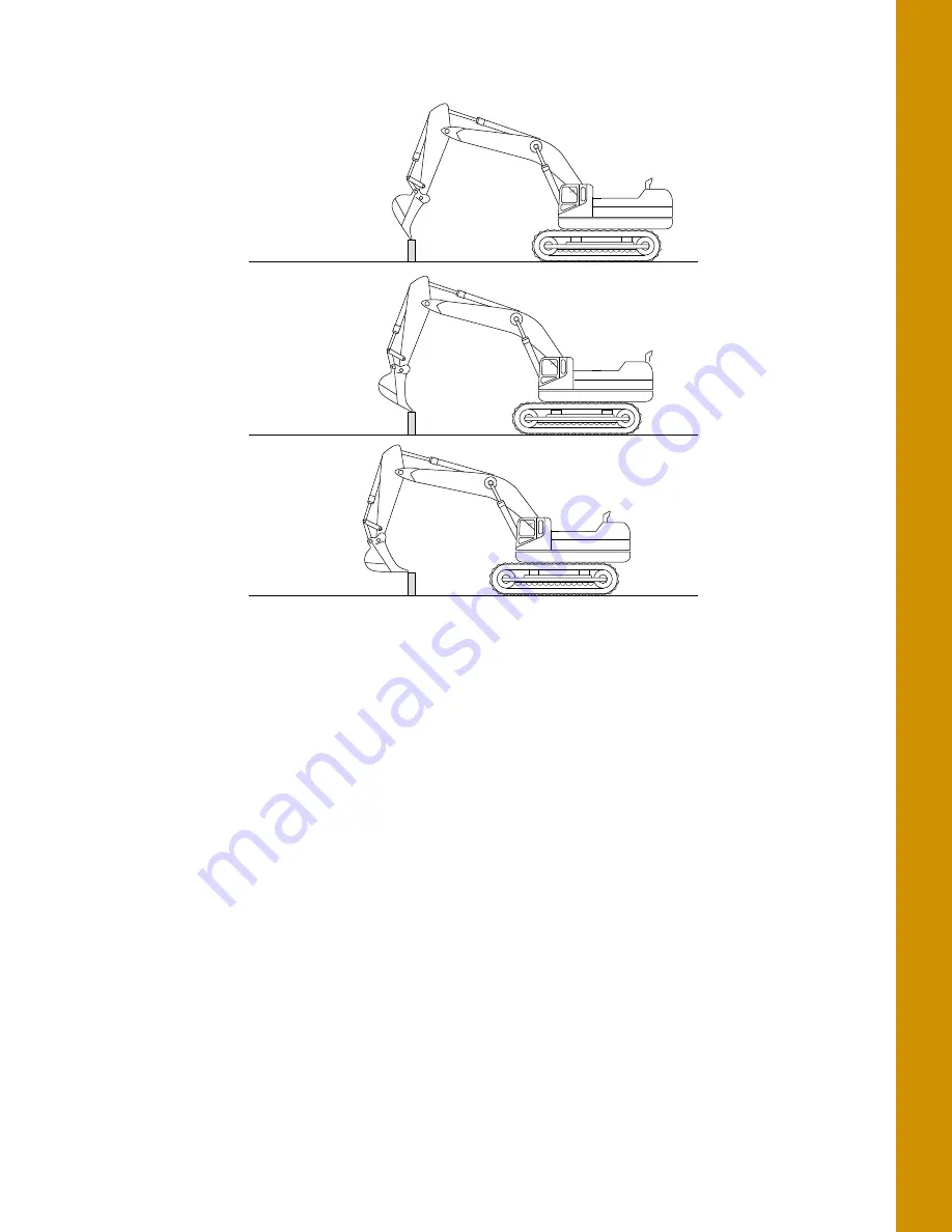
Record Bucket Positions with Boom and Stick in Mid-extension
Bucket extended
Bucket mid-position
Bucket curled
Страница 1: ... 9 YDBWBUPS Indicate System Installation and Calibration Manual ...
Страница 2: ... The information contained herein may not be used accessed copied stored displayed sold modified published distributed or otherwise reproduced without express written consent from Topcon For more information contact Synergy Positioning Systems or visit the Synergy Positioning Systems website at www synergypositioning co nz All branches Phone 0800 867 266 Email info synergypositioning co nz ...
Страница 3: ... GR i3 Vibration Mount to Auxiliary 8 Loading GR i3 Firmware 9 Loading GNSS Firmware 11 System Verification 13 Loading EASy Proof Radio Channels 15 Factory Reset for the GR i3 via TRU 17 Configuring SL 100 for MC X1 Communication 20 Installation 21 TS i3 Sensors 21 TS i3 Sensor Orientation 22 CAN Termination 23 Hitch Sensor 24 DogBone Sensor Optional Mounting Location 25 Tilt Bucket Sensor 26 Tilt...
Страница 4: ...htbars 42 Configuration Complete 43 Calibration 44 Sensor Filtering 44 Body Sensor 45 Boom Sensor 47 Secondary Boom Sensor Optional 48 Stick Sensor 49 Excavator Hitch 50 DogBone Sensor 50 On Hitch Coupling 52 Attachment Edge 53 Multiple Attachments 54 Tilt Bucket 55 Tilting Rotating Bucket 58 Calibrating the LS B10W 59 Setup Verification 60 Testing Machine Element Sensors for Accuracy 60 String Li...
Страница 5: ...nector Pinouts 69 GR i3 70 WiFi Antenna 71 WiFi Antenna Magnet Mount 72 Safety Warnings and Regulatory Information 73 General Warnings 73 RF Radiation Hazard Warning 74 Regulatory Information 74 FCC Statements 74 IC Statements 74 Déclaration de conformité IC 75 Voltage 75 Open Source Support 75 ...
Страница 6: ...poration The Bluetooth word mark and logos are owned by Bluetooth SIG Inc and any use of such marks by Topcon Positioning Systems Inc is used under license Other product and company names mentioned herein may be trademarks of their respective owners Disclaimer of Warranty EXCEPT FOR ANY WARRANTIES IN AN APPENDIX OR A WARRANTY CARD ACCOMPANYING THE PRODUCT THIS MANUAL AND THE PRODUCT ARE PROVIDED A...
Страница 7: ...all give TPS immediate notice so that it may seek a protective order or other appropriate remedy Website Other Statements No statement contained at the TPS website or any other website or in any other advertisements or TPS literature or made by an employee or independent contractor of TPS modifies these Terms and Conditions including the Software license warranty and limitation of liability Safety...
Страница 8: ...on has the potential to result in minor personal injury system damage loss of data or loss of warranty Notification that an action has the potential to result in personal injury or property damage Notification that an action has the potential to result in severe personal injury or death ...
Страница 9: ...Table 1 lists the hardware and software components of the indicate systems The MC X1 System Architecture requires all of the sensors to be running on a 500kbps Baud Rate Legacy sensors used in MC R3 MC i3 and MC i4 systems are not compatible with the MC X1 excavator system Ensure that the sensors to be used in the MC X1 system have the correct part number and label denoting the 500kbps Baud Rate T...
Страница 10: ...R i3 GNSS Antenna and a radio module for precise 3D control Figure 1 Machine Components Bucket Hitch Sensor LS B10W Laser Receiver LS B10W Laser Receiver Body Sensor Boom Sensor Stick Sensor Stick Sensor Radio Module GNSS Antenna 2X GX Series Display MC X1 Controller Optional DogBone Sensor P N 1015925 01 S N 1420 XXXXX When installing components use the Topcon supplied fuse or fused power from th...
Страница 11: ...For Tilt Sensors The Main and Auxiliary Aux antennas provide positional and heading information Main antenna determines 3D machine position Aux antenna determines heading using relative position Using TS i3 sensors the 3D position of the bucket is projected from the Main antenna Figure 3 Tilt Sensor Positional and Heading References 0 90 90 Main Antenna Position Aux Antenna provides heading Projec...
Страница 12: ...S BODY BOOM STICK BUCKET HITCH CAN open UNSWITCHED VOLTAGE SUPPLY 1017652 01 9063 1167 XX M12 CAN CABLE 4060 0586 SENSOR TERMINATOR 3020 0623 F M M TEE B A LS B10W LASER RECEIVER AND BRACKET 3020 0526 M M M TEE 4060 0586 SENSOR TERMINATOR GR i3 ANTENNA RADIO MC X1 GR i3 ANTENNA BODY BOOM STICK BUCKET HITCH CAN open J1939 SERIAL TS i3 500 TILT SENSORS UNSWITCHED VOLTAGE SUPPLY 1017652 01 1026213 01...
Страница 13: ...b interface of the MC X1 Figure 6 Figure 6 Access Topcon Sitelink3D Gateway Web Interface When prompted for the user name and password enter admin for both Figure 7 Figure 7 Enter Sitelink3D User Name and Password Connecting to the MC X Web Interface via MCXCONFIG MCXCONFIG is also know as the MC X Machine Control Gateway 1 Download the MCXCONFIG installer file from myTopcon https www topconpositi...
Страница 14: ...d in the General Device Configuration screen Figure 8 Figure 8 General Device Information Upgrading MC X1 Firmware 1 To upgrade MC X1 firmware click Settings Firmware 2 Click the Choose File button Windows Explorer appears 3 Locate and select the appropriate controller firmware for the MC X1 4 Click Load Firmware to begin Figure 9 Load Firmware Choose File x x Do not close the web browser or power...
Страница 15: ...ngs including any user defined settings This step is recommended if the history of the unit is unknown or if it has been upgraded from any early beta version of the MC X1 firmware 1 From the menus on the left of the screen click Settings Advanced and then click the Administration tab 2 In Erase persistent data row select Application from the drop down list 3 Click Erase Figure 11 Firmware 4 Locate...
Страница 16: ...ilder and tap Finish 3 Ensure the correct machine file is selected on the Machine files page and tap OK Now your mx3 is deployed and the necessary sensors will populate in the MC X Machine Control Gateway Sensors menu 4 Open MCXCONFIG 5 Disconnect the CAN cable from the bottom of the Main GR i3 Vibration Mount on the Left side of the machine 6 From the menus on the left of the screen click Sensors...
Страница 17: ...unt is set to AUX Figure 13 Right 9 Reconnect the CAN cable to the main GR i3 Vibration Mount on the Left side of the machine Loading GR i3 Firmware 1 Select the GR i3 menu under Sensors Figure 14 Sensors GR i3 The GR i3 units are not assigned Main or AUX Only a Vibration Mount may be assigned to be AUX The GR i3s remain interchangeable ...
Страница 18: ...r Indicate System P N 1022461 01 2 Select the Firmware Upgrade tab Figure 15 Firmware Upgrade 3 Select Choose File Figure 16 and navigate to the GR i3 firmware file bin extension 4 Choose Upgrade and the firmware upgrade process should begin Figure 16 Figure 16 Choose File ...
Страница 19: ...461 01 A notification appears once the upgrade process is complete Figure 17 Figure 17 Firmware Upgrade Successful 5 Select AuxGRi3 under the Sensors tab and repeat steps 2 through 4 for the Auxiliary antenna Loading GNSS Firmware 1 Select the GR i3 menu under Sensors Figure 18 GNSS Firmware GR i3 ...
Страница 20: ...Select the GNSS Firmware Upgrade tab Figure 19 GNSS Firmware Upgrade Tab 3 To choose the RAM file select Choose File and navigate to the GR i3 firmware file ldr extension 4 To choose the Flash file select Choose File and navigate to the GR i3 firmware file ldp extension Figure 20 GNSS Firmware Choose File ...
Страница 21: ... appears once the upgrade process is complete Figure 21 GNSS Firmware Upgrade 6 Select AuxGRi3 under the Sensors tab and repeat steps 2 through 5 for the Auxiliary antenna System Verification Now that all necessary firmware has been loaded onto the MC X1 CAN communication can be verified 1 Ensure all sensors and GR i3s are connected then tap on CANOpen Bus Figure 22 CANOpen Bus ...
Страница 22: ...n the Status window Figure 23 Figure 23 CANOpen Bus Communicating Devices Status Once a machine builder has been made active with the correct sensor designations see Calibration on page 44 the Body Boom Stick and Attachment will be selectable in the Sensors menu as shown in Figure 24 on page 14 Figure 24 CANOpen Bus Communicating Devices Status ...
Страница 23: ... is selected as the radio type Figure 25 UHF Radio Setup 2 Navigate to the end of the machine builder and tap Finish 3 Ensure the correct machine file is selected on the Machine files page and Tap OK Now your mx3 is deployed and the radio will populate in the MC X Machine Control Gateway 4 UHF RADIO will not populate in the MC X Web Interface unless an mx3 file with the Satel EASy Proof radio type...
Страница 24: ... enter the appropriate values and tap Save Figure 27 UHF Radio Setup A notification appears when the values are saved Figure 28 Figure 28 UHF Radio Setup Saved 7 Close MCXCONFIG 8 Open 3D MC and tap Tools Configure Radios Configure and then select the appropriate channel from the drop down menu 9 Tap Set Figure 29 UHF Radio Configuration ...
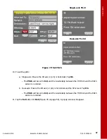
Страница 25: ...ory Reset does not delete any files from the receiver and does not reset modem parameters Perform a Factory Reset after loading a new GNSS firmware file and sometimes to eliminate communication or tracking problems After performing the procedure the receiver requires some time to collect new ephemerids and almanacs up to 15 minutes To perform a Factory Reset using Topcon Receiver Utility TRU 1 Ope...
Страница 26: ...e name to which the GPS receiver board is connected a If a Device name has not been configured tap Then press and hold on the white area of the screen b Select Add The Network Connection screen appears c Enter a Name to identify the Main GNSS board d Enter the following network parameters for the GR i3 Main GPS board IP Address or Host Name 192 168 0 1 TCP Port 8012 Password TPS e Tap Ok MC i3 MC ...
Страница 27: ...1 6 After resetting the Main GNSS board repeat steps 3 to 5e for the Auxiliary GNSS board The TCP Port for the Auxiliary GNSS board is 8013 Figure 32 TRU Network Parameters 7 Tap Connect 8 Tap the Tools icon 9 Select Factory Reset 10 A popup message appears Tap OK 11 After both GNSS boards have been reset close TRU ...
Страница 28: ...on with the MC X1 To communicate with the MC X1 SL 100 Firmware 1 15 must be installed on the SL 100 Refer to the SL 100 Configuration Manual P N 1000226 01 to load the firmware Once the SL 100 is connected the Sitelink3D Gateway is accessible under Network Figure 33 Sitelink3D Gateway To return to the MC X Machine Control Gateway click Back Firmware cannot be loaded while the SL 100 is connected ...
Страница 29: ...note of the direction of the arrow marker on the serial label located on the top of the sensor This direction is needed during calibration The calibration process uses 3D MC to enter direction orientation and other sensor variables Before installation note the following Check the sensor s serial numbers before installing The last two digits of the serial number determine the sensor CAN address and...
Страница 30: ...e machine makes for a cleaner looking installation All tilt sensor orientation is determined when the implement is horizontal zero degrees The orientation of each tilt sensor is entered in 3D MC It is recommended that the sensors be installed on the boom stick and attachment implements with serial numbers in ascending or descending order When entering sensor information make note of each sensor s ...
Страница 31: ...t also connect to the F M M Tee Figure 36 Figure 36 Hard Terminator on F M M Tee 2D System On a 3D system the hard terminator must also connect to the M M M Tee at the last GR i3 usually the AUX as shown in Figure 37 Figure 37 Hard Terminator M M M Tee 3D System BODY BOOM STICK BUCKET HITCH 4060 0586 SENSOR TERMINATOR MC X1 CAN open UNSWITCHED VOLTAGE SUPPLY 1017652 01 3020 0623 F M M TEE 4060 058...
Страница 32: ...Bone itself see DogBone Sensor Optional Mounting Location on page 25 If no hitch sensor is used select None hanging attachment When mounting the attachment sensor keep the following in mind Figure 38 Position the hitch on the ground bucket flat on the ground before mounting the sensor Mount the sensor between the attachment pivot pin and the linkage pin as shown in Figure 38 Sensor is orientation ...
Страница 33: ...f the DogBone will provide additional protection Mounting the sensor on the DogBone requires additional calibration steps The recommended location of the sensor is on the left side of the DogBone Figure 39 DogBone Sensor Mounting Example Installing the sensor on the inside of the DogBone may not be possible on smaller machines due to space constrictions If using the DogBone mounting option worn jo...
Страница 34: ...llowing brands of supported Tilting Rotating attachments include Rototilt Engcon Steelwrist Each manufacturer has specific installation documentation which is required for setup and calibration If using a single axis TS i3 sensor mount the sensor vertically with the label front arrow right or label back arrow right from the cab perspective If using a dual axis TS i3d sensor mount the sensor with a...
Страница 35: ...ate a convenient surface to mount the sensor Mounting the sensor close to the top of the stick will help prevent damage during digging The mounting location shall be on the left or right side of the stick from the cab point of view Figure 41 TS i3 Stick Sensor Mounting Correct Side Location ...
Страница 36: ...e to place the sensor at a location away from the boom pivot Figure 42 Boom Sensor Mounting Secondary Boom Sensor The secondary boom sensor mounting locations are identical to the primary boom sensor mounting locations If a second boom is installed see the previous section Boom Sensor on page 28 Placing the boom sensor on a tapered section will cause calculation errors CL Correct Parallel Location...
Страница 37: ...ounting Top View LS B10W The LS B10W Laser Receiver and bracket must be mounted on the left side of the stick The following section describes bracket mounting cable routing and LS B10W Laser Receiver mounting 1 Before installing the LS B10W bracket you must assemble the bracket kit see the LS B10W Indexing Bracket Assembly Instructions p n 7030 1370 for more information 2 Install the LS B10W onto ...
Страница 38: ... in Figure 44 Figure 44 LS B10W Cable Routing MC X1 Controller Install the MC X1 Controller onto the machine s body using the magnet mounts provided and connect the cable to the GX Series Display S B10W Laser Receiver Setup LS B10W Laser Receiver LS B10W Cable Attachment Sensor Cable Stick Sensor Cable ...
Страница 39: ...Antenna Pole Mount Weld Mount Locations 2 Repeat Step 1 on the opposite side of the excavator 3 Install the two antenna poles onto the weld mount using the three 3 bolts as shown in Figure 46 Various makes and models may require fabrication of mounting surface for the Antenna Pole Mount Ensure that the top of the antenna is flush or slightly above the cab roof when mounted Weld Mount Locations on ...
Страница 40: ... 46 Antenna Pole Installed 4 Install the strain relief brackets Remove the two 2 small bolts to route the TURK CAN cable through the bracket Ensure enough cable is routed through so that the cable can be threaded into the GR i3 BASE Figure 48 on page 33 Figure 47 Strain Relief Mast Weld Mount ...
Страница 41: ...ct the cable Figure 48 on page 33 Figure 48 GNSS Antenna Installed on Pole WiFi Antenna and Magnet Mount If Purchased 1 Install the WiFi Antenna Magnet Mount onto the machine s cab 2 Install the WiFi Antenna onto the Magnet Mount 3 Connect the WiFi Antenna cable to the MC X1 GR I3 GNSS Antenna Mast Strain Relief Bracket Cable Antenna Vibration Mount Weld Mount Bolt 3X ...
Страница 42: ...achine builder and write your measurements on the lines at the side of the following screen captures GR i3 Incorrect measurements or data entry errors have a direct affect on excavating accuracy Take each measurement twice to ensure accuracy GR i3F GNSS Antennas GR i3F GNSS Antenna Heights Note Take the Antenna Above measurement from the bottom of the GR i3 the top of the Vibration Mount Boom Body...
Страница 43: ... 01 Body and Boom Stick Hitch Boom Length Secondary Boom Length Boom Sensor ID Body Sensor ID Θ KƌŝĞŶƚĂƟŽŶ Secondary Boom Sensor ID ƟĐŬ ĞŶŐƚŚ ƟĐŬ ĞŶƐŽƌ Hitch Sensor ID DŽƵŶƟŶŐ ŽĐĂƟŽŶ The Hitch Sensor may be mounted on the Dogbone or the Hitch Coupling Hanging Attachment may be selected if there is no sensor ...
Страница 44: ...ƚŚ ĂŶĚ ĞŶŐƚŚ ƌĞƉĞĂƚĞĚ ĨŽƌ ĞĂĐŚ ďƵĐŬĞƚͿ EŽƚĞ DƵůƟƉůĞ ĂƩĂĐŚŵĞŶƚƐ ŵĂLJ ďĞ ƐĞƚ ƵƉ Ăƚ ĂŶLJ ƟŵĞ tŚĞŶ ƌĞĂĚLJ ĨŽƌ ƵƐĞ ĞŶƐƵƌĞ ƚŚĂƚ ƚŚĞ ĚĞƐŝƌĞĚ ĂƩĂĐŚŵĞŶƚ ŝƐ ĐĂůŝďƌĂƚĞĚ ƐĞĞ ƉŐ ϯϱͿ ZĞĐŽƌĚ ĞŶƐŽƌ ĂŶĚ ŽƌŝĞŶƚĂƟŽŶ ĨŽƌ Ăůů ƐĞŶƐŽƌƐ Note Length 3 is the length ĨƌŽŵ ƚŚĞ ĂƩĂĐŚŵĞŶƚ ƉŝǀŽƚ ƉŝŶ ƉĞƌƉĞŶĚŝĐƵůĂƌ ƚŽ ƚŚĞ Ɵůƚ ƉŝǀŽƚ ƉŝŶ Ĩ ƚŚŝƐ ŵĞĂƐƵƌĞ ŵĞŶƚ ŝƐ ŝŶĐŽƌƌĞĐƚ ƚŚĞ ĂĐĐƵƌĂĐLJ ŽĨ ƚŚĞ ĂƩĂĐŚŵĞŶƚ ǁŝůů ďĞ ĚĞŐƌĂĚĞĚ ĂƐ ŝƚ ŝƐ ƟůƚĞĚ ĞŶƐ...
Страница 45: ...tem P N 1022461 01 LS B10W ƩĂĐŚŵĞŶƚ ĞƚƵƉ ůĂŵƐŚĞůů ƵĐŬĞƚ ƩĂĐŚŵĞŶƚ ĞƚƵƉ dƌĂƉĞnjŽŝĚĂů ƵĐŬĞƚ ƩĂĐŚŵĞŶƚ ĞƚƵƉ ƌŝŶĚŝŶŐ tŚĞĞů ĞƉƚŚ ĨƌŽŵ ĞŶƚĞƌůŝŶĞ ŽĨ ƟĐŬ Distance from Bucket Pivot to LSB10W Distance from Left of Pivot Angle to the Stick Centerline Note Only determinded during calibration of the machine ...
Страница 46: ...n of the sensor mounting Step 1 Configure the Machine File and the excavator options 1 In the GX Series display tap the Power Button Control Machine setup 2 Select a current machine file and tap Edit or tap New to create a new machine file 3 On the Configuration name type screen enter or select the appropriate data as needed Figure 49 Figure 49 Configuration name type 4 Tap Next to navigate to the...
Страница 47: ...p Next to navigate to the Boom Body 1 screen Enter the appropriate values 7 If using a TS i4 as a compass select TS i4 from the drop down menu Then tap the Wrench icon to calibrate the compass Follow the on screen instructions 8 Tap Next to navigate to the Boom Body 2 screen Enter the appropriate value Step 2 Designate each sensor to its corresponding implement If using a TS i4 TS i4 IMU will be s...
Страница 48: ...creen Figure 51 Figure 51 Select Body and Boom Sensor ID 2 Tap the appropriate Sensor ID box and select the serial number last two digits of the sensor corresponding to the machine element 3 Enter the appropriate values 4 Tap Next to access the Excavator Stick screen Figure 52 Select Stick Sensor ID 5 Enter the appropriate values and select the corresponding sensor ...
Страница 49: ...cess the Excavator Attachments screen a Tap New to access the Excavator Attachment Setup screen b Enter or select the appropriate data as needed Figure 54 Excavator Attachments c Press Next to access the Calibrate Attachment Angle screen calibration performed in next chapter d Press Next to access the Calibrate Bucket Base screen calibration performed in next chapter e Press Finish to access the E...
Страница 50: ...ndicate System P N 1022461 01 Audible Guidance 1 Tap Next to access the Audible Guidance screen 2 Enter the desired Tone and Duration settings Figure 55 Audible Guidance Lightbars 1 Tap Next to access the Light Bars screen 2 Enter the desired settings Figure 56 Lightbars ...
Страница 51: ...e 43 Excavator Indicate System P N 1022461 01 Configuration Complete 1 Tap Next to access the Configuration Complete screen 2 Press Finish to save configuration or press Cancel to return to the Machine Files screen without saving Figure 57 Configuration complete ...
Страница 52: ...Excavator Hitch screen 2 Tap the Wrench icon next to Sensor ID Figure 58 3 Select a filtering level and tap OK Figure 58 4 Navigate through the remaining steps of Machine Setup then save the file and exit 3D MC Figure 58 Set Filtering Level If using the DogBone mounting option worn joints in the DogBone linkage will cause decreased accuracy The best practice is to perform the machine calibrations ...
Страница 53: ...setup 2 Select the appropriate machine file and tap Edit 3 Continue to press Next to access the Excavator Frame Sensors screen 4 Tap the Wrench icon for the body sensor 5 Tap the Orientation box and select the physical orientation of the mounted sensor tap OK Figure 59 Select Sensor Orientation Orientation is Label up with the arrow pointing one of the four directions The body sensor calibration r...
Страница 54: ...e free of obstructions 7 Curl the stick and bucket in as close as possible to reduce tipping errors 8 Rotate the body parallel to the tracks Position 1 as shown in Figure 60 9 Tap Set next to Pitch enter the value as zero and tap Set again Figure 61 repeat for the Roll value Figure 61 Set Pitch and Roll Values to Zero Rotate 180 Position 2 Starting Position Position 1 ...
Страница 55: ... a laser is recommended to correctly position the boom at zero degrees 1 Tap the Wrench icon that corresponds to the boom sensor Figure 64 2 Select the correct orientation from the drop down menu 3 Ensure the machine is parked on a flat and stable surface and that the Body Sensor reads a 0 0 degree roll 4 Place a zero slope rotating laser along the side of the machine to shine on both the boom piv...
Страница 56: ...alue as zero and tap Set again Figure 64 Figure 64 Set Pitch Value to Zero 9 Tap OK to return to the Excavator Frame Sensors screen Secondary Boom Sensor Optional The secondary boom sensor uses the same calibration method as the primary boom sensor 1 Check the Secondary Boom check box Figure 65 and see Boom Sensor on page 47 for instructions on calibrating the secondary boom sensor Figure 65 Secon...
Страница 57: ...ck sensor Figure 67 on page 50 2 Select the correct orientation from the drop down menu 3 When performing the stick sensor calibration position the stick at 90 degrees 90 degrees is accomplished when the Bucket Pivot Pin is directly under the Stick Pivot Pin A magnet and plumb bob is recommended for this step 4 Position the stick at 90 Figure 66 on page 49 Figure 66 Stick at 90 ...
Страница 58: ... extra steps before calibrating the bucket this procedure will be discussed first DogBone Sensor When performing the DogBone sensor calibration a builder s level is required to correctly position the DogBone at zero degrees 1 Tap the Wrench icon that corresponds to the DogBone sensor Figure 68 If mounting the hitch sensor directly on the attachment or inside the quick release coupler skip to On Hi...
Страница 59: ...e horizontal using a builder s level 4 Once the DogBone is square and level tap Set next to Pitch enter 0 00 and tap Set Figure 69 Set Pitch Value to Zero 5 Tap OK the Excavator DogBone screen appears Figure 70 6 Tap the Wrench icon the DogBone Calibration screen appears 7 Ensure that the angle between the DogBone and line between the DogBone pivot pin and the attachment pivot pin is still 90 degr...
Страница 60: ...ermine Stick Angle Difference 9 If this is the last sensor physically connected to the machine see CAN Termination on page 23 On Hitch Coupling 1 When performing the on hitch coupling sensor calibration position the bucket at 90 degrees Figure 71 On Hitch Coupling Stick Angle Difference ...
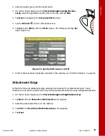
Страница 61: ...nd tap Set again Figure 72 Figure 72 Set the Pitch Value to 90 0 7 If this is the last sensor physically connected to the machine see CAN Termination on page 23 Attachment Edge Perform the following attachment edge calibration procedures for all attachment types These calibrations must also be performed for each individual attachment when using multiple attachments 1 On the GX Series display tap t...
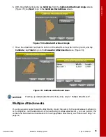
Страница 62: ...t on the ground and tap Calibrate tap Finish to go to the Excavator Attachments screen Figure 74 Figure 74 Calibrate Attachment Base Multiple Attachments If a using a quick coupler to switch attachments mount the sensor to the quick release mechanism or the DogBone not the attachment When calibrating multiple attachments you must perform the vertical and flat attachment calibrations for each appli...
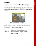
Страница 63: ...h and Length Figure 75 4 Enter a value for the tilt bucket Length 3 and select a Sensor ID for the tilt bucket sensor Figure 75 Enter Tilt Bucket Measurements 5 Using a carpenter s level adjust the bucket until the tilt pin is horizontal 6 Using a carpenter s level adjust the cross slope of the bucket until the bucket is level 7 In 3D MC tap the Wrench icon next to the Sensor ID 8 Select the senso...
Страница 64: ...is TS i3 For both single axis TS i3 Sensor and dual axis TS_i3d sensor follow steps 9 to 12 For tilt bucket always use the SET buttons to calibrate the tilt bucket In calibration steps 9 to 12 3D MC calculates the relation or position between the hitch and tilt bucket sensor and stores the value Even when dual axis TS i3d sensor for tilt bucket is used the pitch will be used from the hitch sensor ...
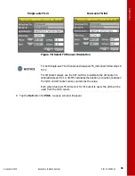
Страница 65: ...e set to 0 0 and the relationship between the Tilt Pivot and the Hitch sensor is recorded b Dual axis Ensure the tilt axis or pin is horizontal and the tilt is level Tap Ok The Pitch will be set to 0 0 and the relationship between the Tilt Pivot and the Hitch sensor is recorded 11 Tap the Set button for Roll Figure 78 on page 58 A popup screen will appear Single axis TS i3 Dual axis TS i3d ...
Страница 66: ...ll be set to 0 0 and the relationship between the verticality of the tilt sensor and Hitch sensor will be recorded b Dual axis TS i3d The Tilt Sensor should be horizontal label facing up Ensure the Tilt Pivot is level and the Tilt is zero Tap Ok The roll will be set to 0 0 13 Tap Ok to finish this calibration Tilting Rotating Bucket Refer to the Installation and Setup manual from the manufacturer ...
Страница 67: ...ments for the LS B10W Figure 79 Depth to center of stick enter the measurement for the distance between the middle of the stick to the light cells on the LS B10W From bucket pivot enter the measurement for the distance from the along the projected line between the bucket pivot and stick pivot at the point where the LS B10W is perpendicular to the projected line Figure 79 Left of pivot line enter t...
Страница 68: ...dinates with the following machine positions facing North 2 Then rotate 180 and record each position again facing South Record Bucket Positions with Boom and Stick Fully Extended It is your responsibility to be completely familiar with the cautions described in these installation instructions These messages advise against the use of specific methods or procedures which can result in personal injur...
Страница 69: ...rification Testing Machine Element Sensors for Accuracy 61 Excavator Indicate System P N 1022461 01 Record Bucket Positions with Boom and Stick in Mid extension Bucket extended Bucket mid position Bucket curled ...
Страница 70: ... reference The difference should be within 0 2Ft String Line Verification The following sections describe setting up a string line to test the sensor accuracy Setup 1 Set a zero slope using a laser 2 Set up a string line the length of the machine s reach and then set up the string level 3 Utilize the measure slope feature to perform the following test For more information on the Measure Slope func...
Страница 71: ... second point screen of the Measure Surface feature The sloping surface created by 3D MC should match the slope of the string line as set by the laser 5 Position the bucket on the string at several points and compare the cut fill readings shown in 3D MC cut fill readings should be zero for each position Figure 80 Figure 80 Move the Bucket and Compare 3D MC Measurements 6 If the measurements read z...
Страница 72: ... Curl only the bucket in and out in various positions and measure the distance from the string line to the bucket teeth a with measuring tape Figure 81 Figure 81 String Line Verification Bucket 4 Compare the measuring tape values with those shown in 3D MC 5 If the measurements compared against 3D MC match there could be an issue with one of the other sensors repeat steps 1 4 and reverify 6 If the ...
Страница 73: ...l match follow the steps in Boom Sensor below 7 If the measurements compared against 3D MC do not match each sensor must be evaluated for machine measurement or calibration errors Boom Sensor 1 Position the bucket above the string line so that the bucket teeth or edge are at their closest point to the string 2 Place the bucket teeth or edge on the string and zero the bucket in 3D MC 3 Curl only th...
Страница 74: ...ransmit a flat plane beam 2 Set flat string line and measure the distance from the laser plane to the string line using a grade rod with laser receiver Figure 84 Laser Plane to String Line Measurement Distance from laser plane to string line _________________________ 3 Create a 0 Known Slope Surface in 3D MC by tapping the Topcon Logo button Tools Known Slope ensure grade is 0 00 and tap OK 4 Plac...
Страница 75: ... 01 Figure 85 Zero to Laser 6 Touch the bucket tooth to the string and verify grade Figure 86 Laser Plane to String Line Measurement 7 Track the machine to a different location Perform the Zero to laser function again 8 Touch the bucket tooth to the string and verify grade ...
Страница 76: ...netic Compatibility Applicable Standards Emissions Applicable regulation EN 13309 2010 ISO13766 2006 EN 55032 2012 Immunity Applicable regulation EN 13309 2010 ISO 13766 2006 EN 301 489 1 Switched Output Power 5A sensor conditioned output power Ports 1 ea port RS232 Digital IO 2 ea Ethernet 2 ea CAN Wireless WIFI 802 11abgn and BT 2 0 BLE 4 1 Environmental Operating Temperature 40 C 40 F to 80 C 1...
Страница 77: ...und 3 Ethernet TX 4 Conditioned Power Out 4 Ethernet TX 5 Ignition input HW interlock and input to CPU 5 CAN 2 Low 6 Ground 6 CAN 2 High 7 Ethernet RX 7 Conditioned power out 8 Ethernet RX 8 Ground 9 Ethernet TX 9 Ground 10 Ethernet TX 10 Digital In Out RS 232 RX PPS Event In Out 11 CAN 1 L 11 Digital In Out RS 232 TX PPS Event In Out 12 CAN 1 H 12 Conditioned Power Out Conn A Conn B 7 6 12 7 6 1 ...
Страница 78: ...pacitively coupled Ports CANopen Wireless BT 2 0 BLE 4 0 Environmental Operating Temperature Wired Operation via CAN 40 C 40 F to 80 C 176 F Wireless Operation 30 C 22 F to 60 C 140 F Moisture Test NA Ingress Protection IP67 Shock Test 25G 11 ms sine wave each axis Salt Fog Test ASTM B117 03 Vibration Test 10 2000Hz Random 7 7 GRMS 8 hours each axis Physical Housing Magnesium alloy and PBT PC Allo...
Страница 79: ...GPS H 0 3 m V 0 5 m SBAS H 0 8 m V 1 2 m RTK H 5 mm 0 5 ppm x baseline V 10 mm 0 8 ppm x baseline RTK Initialization Time 10 seconds RTK Initialization Reliability 99 Conn A 9 pin Pogo 1 Power 2 CAN H 3 CAN L 4 5 6 7 8 Wire DN 9 Ground Table 3 GR i3 Specifications Table 4 WiFi Antenna Specifications General Specific Frequency 2400 2500 MHz Gain dBi 3 dBi Mobile Antenna Mounting Type NMO Antenna Ma...
Страница 80: ...1 Manufacturer LAIRD TECHNOLOGIES Manufacturer P N GB195RPSMAI Table 5 WiFi Antenna Magnet Mount Specifications General Frequency Range 0 6 GHz Mounting Type Magnetic base NMO mount Installation Metallic magnet mountable surface Operating Temperature 40 C 40 F to 85 C 185 F Cable Type Low loss double shielded ATX195 Cable Length 12 ft 3 65 m Pull Strength 80 lbs ...
Страница 81: ...n the machine is turned off Relieve all pressure in the hydraulic lines before disconnecting or removing any lines fittings or related components If injury occurs seek medical assistance immediately When welding use appropriate precautions and practices After welding all affected areas should be painted with a rust inhibitor Disconnect all Topcon system electrical cables prior to welding on the ma...
Страница 82: ...e the radio certification number only signifies that Industry Canada technical specifications were met Tampering with the unit by the operator or non factory authorized technicians will void the unit s warranty Do not attempt to open the unit and modify any of its internal components Do not short circuit To ensure compliance with FCC and Industry Canada RF exposure requirements this device must be...
Страница 83: ...ieur approuvé pour l émetteur par Industrie Canada Dans le but de réduire les risques de brouillage radioélectrique à l intention des autres utilisateurs il faut choisir le type d antenne et son gain de sorte que la puissance isotrope rayonnée équivalente PIRE ne dépasse pas l intensité nécessaire à l établissement d une communication satisfaisante Ce matériel respecte les standards RSS exempt de ...
Страница 84: ...ª 5PQDPO PSQPSBUJPO BUJPOBM SJWF t JWFSNPSF t Specifications subject to change without notice All rights reserved 3FW Draft 0 1 www topconpositioning com ...