6
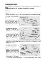
tighten. In upper outer side, using Bolt M10X165 (A6) that was assembled on frame to
tighten.(Attention: bolt head position is the front underside. See figure 3-1)
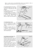
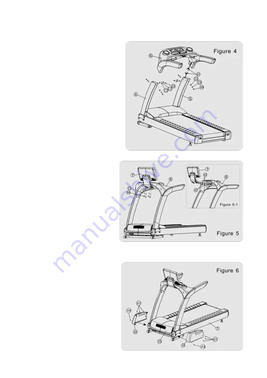
4. Assembling handlebar and controller
A. Connect the Signal wire from Right
upright tube to corresponding wires from
Handlebar.
B. Install handlebar and controller set(6) to
the Left/Right upright tube (4,5).
C. Connect handlebar and controller(6) to
the Left/Right upright tube (4,5) using 8 sets
of Half-round bolt M10X20(A8),Spring
washer
φ
10(C5),Flat washer
φ
10(C2).
(Attention: To align screw hole)(See figure 4)
5. Assembling display screen
A. Connect the signal wire from display
screen to corresponding wire from
controller. Crowding the extra wire into
controller.
B. Connect the display screen (7) to
handlebar and controller (6) using 4 sets
of Half-round bolt M10X20(A8),Flat
washers
φ10(
C2).(Attention: To align
screw hole)(See figure 5)
6. Assembling motor left & right cover
A.Tighten all the assembling bolt.
B.Install motor left cover (24) to left motor
cover (23) of base frame (1) using 1pcs
Crosshead self-lock bolt ST4X30 (A9) in
front and 3pcs Crosshead self-lock bolt
ST4X16 (A17) to tighten.
C.Install motor right cover(25) to left motor
cover(23) of base frame (1) using 1pcs
Crosshead self-lock bolt ST4X30 (A9) in
front and 3pcs Crosshead self-lock bolt
ST4X16(A17) to tighten.(See figure 6)


