background image

Method of Installation (Piping)

-5-

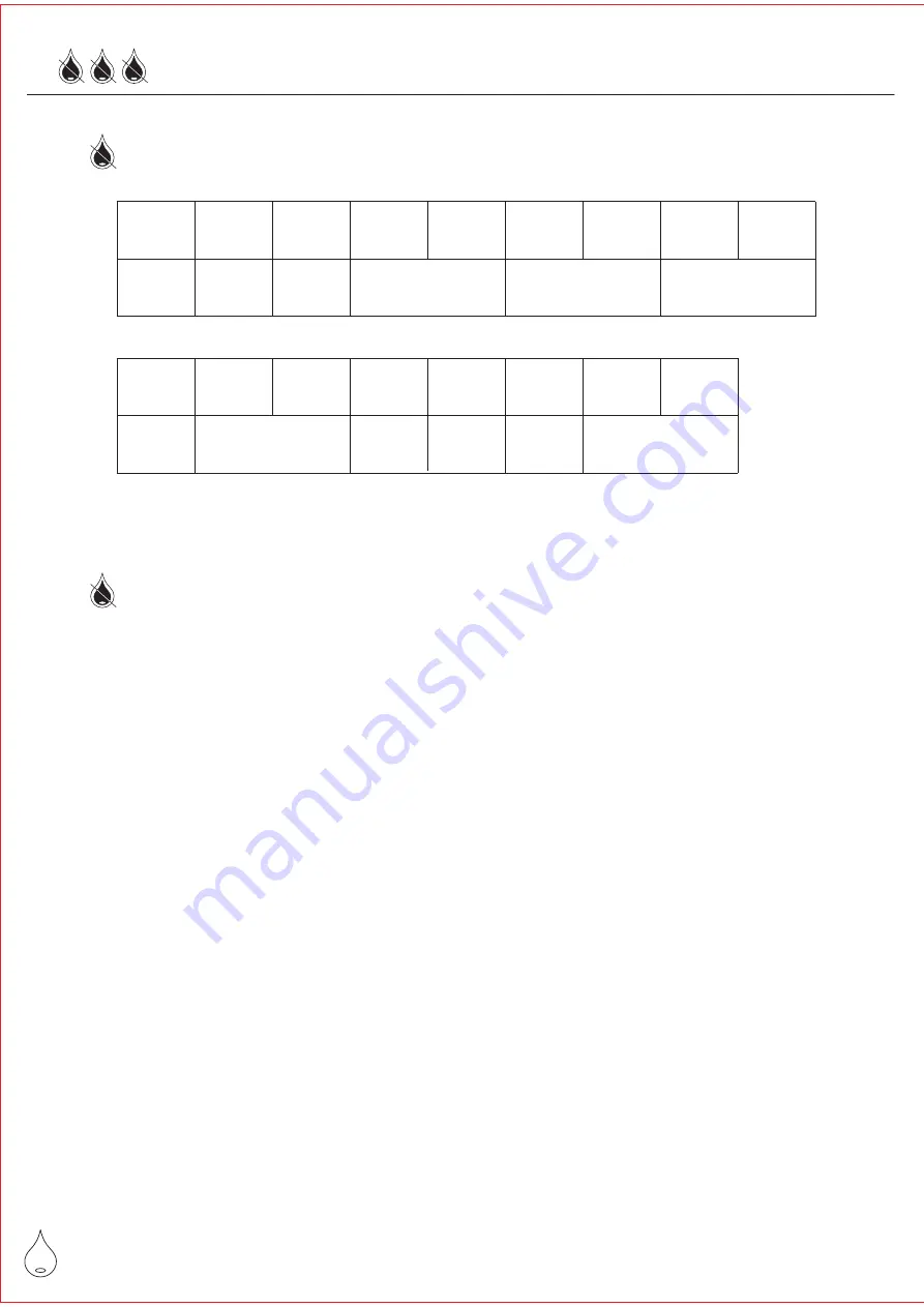
Diameters of Inlet And Outlet Pipes of Dryer

MODE AD-005

AD-010 AD-015 AD-020 AD-030 AD-040 AD-050 AD-060

PT

INCH

1/2"

3/4"

1"

1-1/2"

2"

MODE AD-075S AD-100S AD-150S AD-200S AD-250S AD-300S AD-400S

PT

INCH

2"

2-1/2"

3"

3"

4"FL

Piping Method

1. Please refer to the attached drawing 1 for installation procedures

when there is purifying equipment like gas tank and filter, etc.

2. Diameter of the air inlet and outlet of the dryer is the same. Pay

attention to wrong installation that may reduce the drying efficiency

of the dryer.

3. If the compressor shakes violently while running, install an extra

high-pressure vibration-proof hose unto the connection pipe

between the compressor and the dryer to protect the dryer.

4. Install valve gates and bypass pipes at the inlet and outlet of the dryer

for service and maintenance needs.

5. Diameters of the pipes should not be too small. Avoid long pipes with

many curves to reduce the loss from pressure drop.

6. Keep dust or unnecessary objects away from the air pipes while

installing.

Содержание AD-005

Страница 1: ...Operating Manual Freezing Compressed Air Dryer Http www dryer com tw E mail dryer dryer com tw...

Страница 2: ...ing 1 Diameters of Inlet And Outlet Pipes of Dryer 2 Piping Method 5 Method of Installation Power Distribution 1 Electric Features of Dryer 2 Distribution Lines 6 Method of Operation 1 Inspection Item...

Страница 3: ...ures of Product Features 2 1 Keep the compressed air pressure under the allowable pressure of the dryer 2 Ensure no pressure inside the system before disassembling or installing the pipes for maintena...

Страница 4: ...ying flows out from here Air Outlet Air Inlet Wet compressed air enters from here Control Panel This panel is used for control operation and status display Automatic Wat Drainer rear er Precipitated m...

Страница 5: ...or places where shake violently Do not install at places exposed to the rain Do not install at places with direct sunlight or close to heat sources Do not install at places that exceed rated ambient...

Страница 6: ...let and outlet of the dryer is the same Pay attention to wrong installation that may reduce the drying efficiency of the dryer 3 If the compressor shakes violently while running install an extra high...

Страница 7: ...e it is within the range of 5 of rated voltage see the nameplate 4 Do not share the same protection switch with other equipment 5 Install an extra proper protection switch from electric leakage in acc...

Страница 8: ...ng system is normal 3 Check if operation of the cooling fan motor is normal 4 After the dryer runs for 3 minutes open the valve gates of air inlet and outlet and check if the bypass pipes are tightene...

Страница 9: ...the temperature rises within the range of the blue area which is normal to prevent from icing and freezing Stop 1 Close the valve gates of air inlet and outlet and check if the bypass pipes are tight...

Страница 10: ...ondenser and the fin of the pre cooler clean Fig 2 Fig 1 filter net metal cup acrylic cup condenser Daily Maintenance 9 1 Check the automatic water drainer Fig 1 every day for any blocking or leakage...

Страница 11: ...ent sensor can detect operation status of the compressor when the dryer is running In case of over current the compressor will be stopped at once Protection Device Troubleshooting 1 Can t start Failur...

Страница 12: ...not go through the dryer Check the installed pipes Rated requirements not met Rated air flow exceeds Increase dryer equipment 3 Extreme pressure drop Failure Possible Reason Resolution Improper operat...

Страница 13: ...on Equipment Application 0 01 0 003 0 01 1 By pass Freezing dryer Air compressor Fast drilling general coating planned packaging Cleaning shipping tooling cutting processing 12 5 Air tank Foods medici...

Страница 14: ...AD 020 Control board Variable voltage A Blue B Brown C Red 1 2 3 4 5 6 7 13 Switch Starting capacitor Current starter Overload Alarm Compressor Fan Optional Variable voltage 380 460V to 220V D D White...

Страница 15: ...ature sensor Control board Variable voltage 1 2 3 4 5 6 7 A Blue B Brown 14 E B G F F 95 97 A1 MC 96 98 A2 E E B D A C D D A E Fan Thermal Relay B Overload A E 5 4 2 1 Voltage starter Running capacito...

Страница 16: ...le voltage 1 2 3 4 5 D A E B S R T PE A Blue B Brown C Red D White E Black F Yellow G Orange 15 C D E E D D Set 40 Temperature Switches Fan Compressor Fan Thermal Relay Alarm Running E 1 3 5 4 2 6 95...

Страница 17: ...Footnote 16...

Страница 18: ...Footnote 17...

Страница 19: ...Footnote 18...

Страница 20: ......

Отзывы: