background image

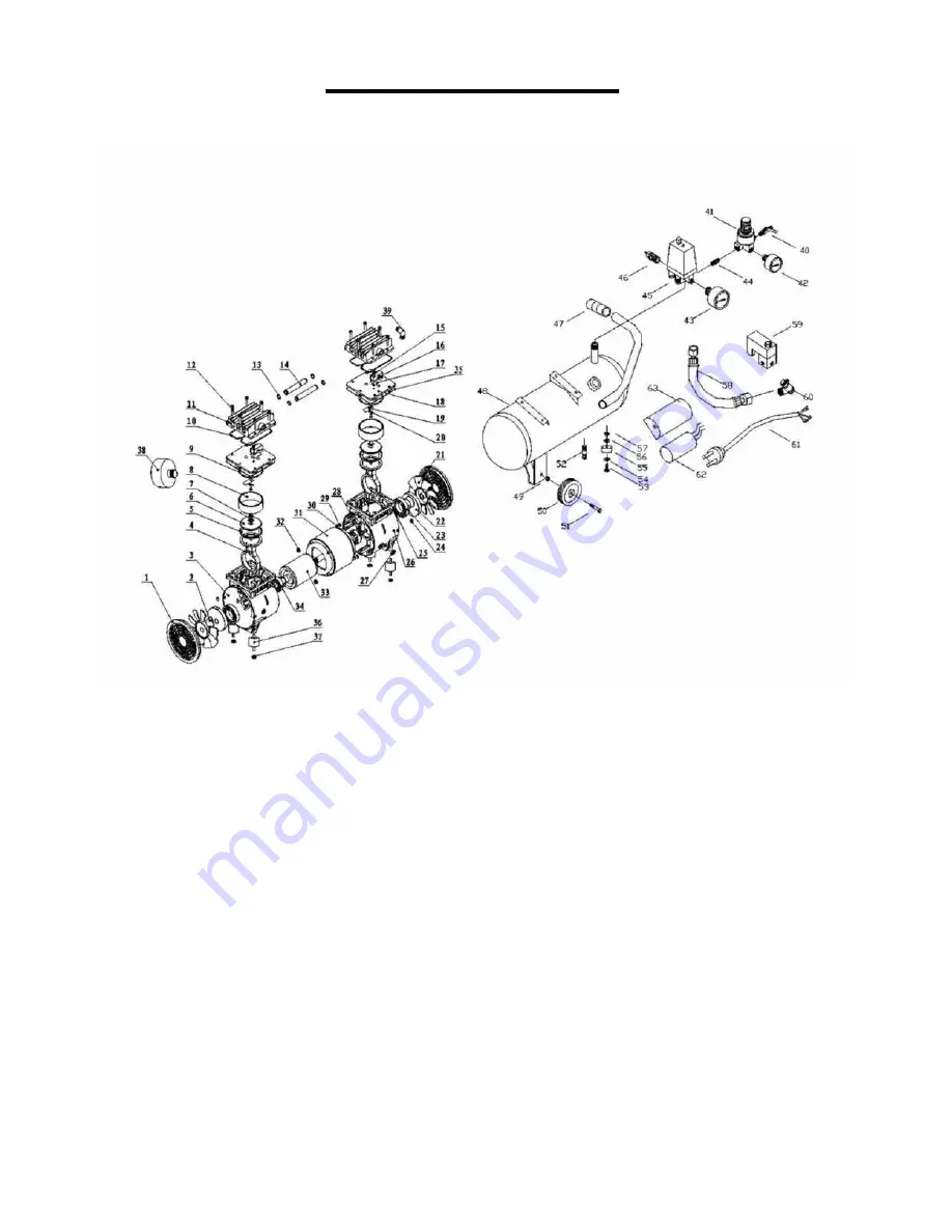
PARTS DIAGRAM

1. Cover

2. Left Fan

3. Left Crankcase

4. Connecting Rod

5. Piston Cup

6. Binder Plate

7. Con Rod Bolt

8. Cylinder

9. Cylinder Seal

10. Head Seal

11. Cylinder Head

12. Head Bolt

13. ‘O’ Ring

14. Transfer Pipe

15. Valve Plate Bolt

16. Valve Block

17. Reed Valve

18. Reed Valve

19. Valve Plate

20. Washer

21. Right Fan

22. Shaft Seal

23. Bearing 6908-2z

24. Bearing Bolt

25. Bearing Bolt

26. Right Crankcase

27. Protection Ring

28. Assembly Bolt

29. Assembly Bolt

30. Spring Washer

31. Stator

32. Assembly Nut

33. Rotor

34. Bearing 6203-2z

35. Adjusting Washer

36. Rubber Mount

37. Spring Washer

38. Air Filter

39. Elbow

40. Deflating Tap

41. Regulator

42. Outlet Pressure gauge

43. Tank Pressure gauge

44. Connector

45. Pressure Switch

46. Safety Valve

47. Handle

48. Tank

49. Wheel Nut

50. Wheel

51. Bolt (Axle)

52. Tank Drain Cock

53. Bolt

54. Washer

55. Cushion Foot

56. Washer

57. Nut

58. Pipe

59. Actuated Valve

60. Non Return Valve

61. Plug and Lead

62. Capacitor

63. Capacitor cover

4.

Содержание Platinum Series

Страница 1: ...OIL FREE AIR COMPRESSOR INSTRUCTION MANUAL Platinum Series 1 ...

Страница 2: ...Risk of Falling Operation of the air compressor should always be in a position that is stable Never use the air compressor on a rooftop or elevated position that could allow the unit to fall or be tipped over Use additional air hose for elevated jobs Risk from Flying Objects Always wear approved safety glasses with side shields when the air compressor is in use Turn off the air compressor and drai...

Страница 3: ...motor and also the cut in cut out pressure settings This switch serves as the Auto On Off positions for the unit 45 Air Intake Filter Provides clean air to the pump and must always be kept free of debris Check on a daily basis or before each use 38 Check Valve When the pump is not in operation the valve closes to retain air pressure inside the tank 60 Pressure Relief Valve The pressure relief valv...

Страница 4: ...Bolt 26 Right Crankcase 27 Protection Ring 28 Assembly Bolt 29 Assembly Bolt 30 Spring Washer 31 Stator 32 Assembly Nut 33 Rotor 34 Bearing 6203 2z 35 Adjusting Washer 36 Rubber Mount 37 Spring Washer 38 Air Filter 39 Elbow 40 Deflating Tap 41 Regulator 42 Outlet Pressure gauge 43 Tank Pressure gauge 44 Connector 45 Pressure Switch 46 Safety Valve 47 Handle 48 Tank 49 Wheel Nut 50 Wheel 51 Bolt Ax...

Страница 5: ...ir or replacement of the cord or plug is necessary do not connect the grounding wire to either flat blade terminal The wire with insula tion having an outer surface that is green with or with out yellow stripes is the grounding wire Check with a qualified electrician or serviceman if the grounding instructions are not completely understood or if in doubt as to whether the product is properly groun...

Страница 6: ...d upon the hours of operation and the working environment Air compressors used in an extremely dirty and or hostile environment will require a greater frequency of all maintenance checks Daily Shut Down Procedures 1 Set the Auto On Off lever to the Off position 2 Unplug the power cord from the receptacle 3 Set the outlet pressure to zero on the regulator 4 Remove any air tools or accessories 5 Ope...

Страница 7: ... when the accessory is used replace the regulator NOTE Adjust the regulated pressure under flow conditions while accessory is being used It is normal for the gauge to show minimal pressure loss during initial use of the tool Excessive tank pressure Move the Auto On Off lever to the Off position If the unit doesn t shut off unplug it from the power source and contact a service technician Motor will...

Отзывы: