2700-4001_22 IMA Manual
11
Last Revision: 12/14/2021
developing the required thrust force and velocity in a variety of applications.
Before installation and commissioning of the equipment, this manual and all accompanying manufacturer
documents and manuals MUST be completely read by the appropriate personnel. All warning texts must be given
special attention.
2.3 Cable Routing
It is recommended that the power and signal cables for Tolomatic IMA Actuators be routed as far apart as possible
to minimize electrical noise in communication cables.
Over time, liquid contaminants such as oil and cleaning solutions may accumulate on the cables and into the
connectors if they are an exposed type. To minimize the introduction of contaminants to the connector, route the
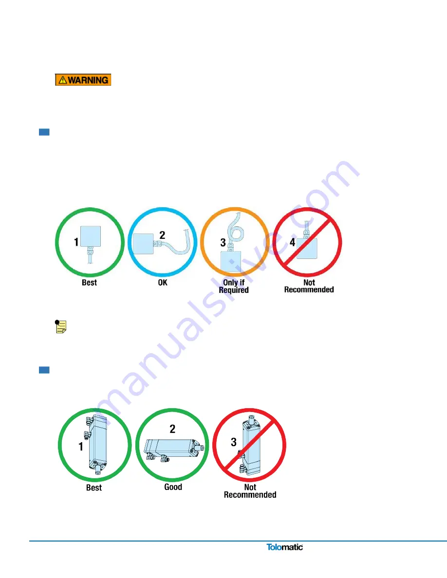
cables so that there is a loop in the cable just prior to its attachment to the connector.
Examples are shown depending on the orientation of the connectors. Units mounted in such a way that the
connectors are on the bottom surface of the actuator require no looping.
Figure 2.3: Recommended routing of Tolomatic IMA Actuator cabling.
The standard cables from Tolomatic are not flex rated and have a minimum bend radius of 3.75 in (95mm). Any
repeated flexing or excessive bending can result in broken conductors and intermittent faults.
2.4 Actuator Orientation
1. Rod End Down (Best) 2. Rod End Horizontal (Good)
3. Rod End Up (Never)
It is not recommended to mount the IMA with the thrust rod pointing upwards. Mounting the thrust rod vertically
increases risk of contamination and ingress..
Figure 2.4:
1. & 2.
Recommended IMA thrust rod orientation is down or horizontal.
3.
Due to increased risk of
contamination and ingress never orient the IMA actuator with the thrust rod up.


