Toa C-RM700 Скачать руководство пользователя страница 34

34

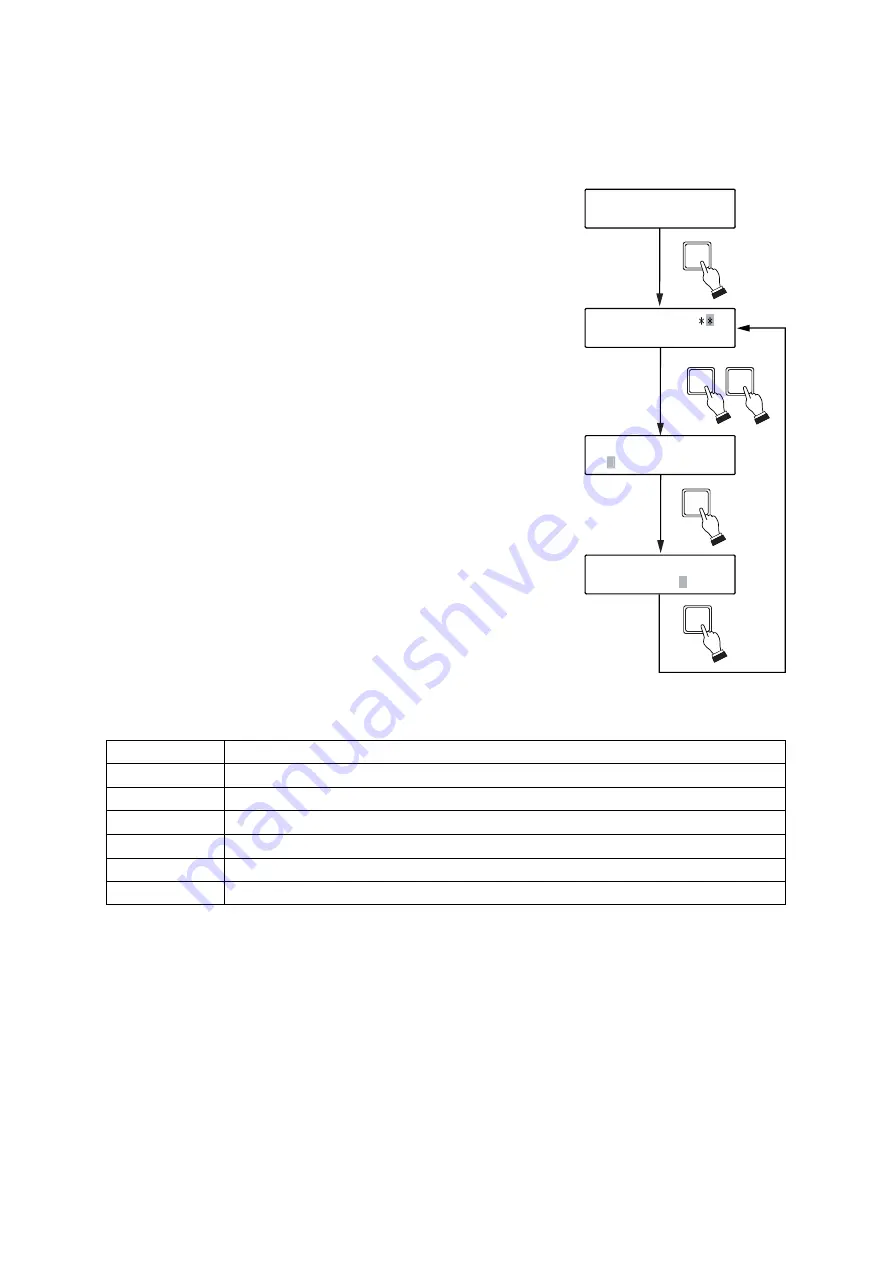
7.4.9. Home position

Sets the Combination camera's state when automatically returned to home position.

1. Press the Menu key for 3 seconds or more to display the menu

screen. 

2. Tilt the joystick up or down to select "HOME POS," then confirm it

with the SET key. 
The channel (camera number) input screen for the Home Position
setting will appear.

3. Enter the channel number with the numeric keypad, and confirm

the entry with the SET key.
The operation setting is displayed on line 2, and the flashing
cursor moves to the position "1" (left).
The indication "1" on the left shows the operation content when
the Home Position selection input terminal in the unit's rear panel-
mounted Alarm output/control input terminal is opened.
Similarly, the indication "2" on the right shows the operation
content when the Home Position terminal is closed. (Refer to

p. 51

, "Alarm Output/Control Input Terminal Connections.")

4. Tilt the joystick left or right to select the operation contents for "1"

from the list shown below and confirm it with the SET key. 
The flashing cursor moves to the position "2" (right).

5. Tilt the joystick left or right to select the operation contents for "2"

from the list shown below and confirm it with the SET key. 

6. To further set other channels, repeat Steps 3-5. To return to the

setting item display, press the Clear key.

H O M E

P O S

C H

H O M E

P O S

H O M E

P O S

7 C H

1   T R A 1

2

P O S 1

H O M E

P O S

7 C H

1   T R A 1

2

O F F

SET

2

7

SET

(Example)

3

4

SET

5

SET

T

POS1

Orients the camera in the direction of Position 1, as set at the camera.

POS2

Orients the camera in the direction of Position 2, as set at the camera.

PAN

Activates the Auto-Pan function.

TRA1 - 8

Activates the Auto Trace function.

P-SEQ

Activates the Preset Sequence function.

TOU1 - 16

Activates the Tour function.

OFF

Disables Home position function.

[Home position selector terminal operation settings]

Note:

This selection is set to "POS1" by the factory.

Notes

• Match the selected home position to the Combination Camera's  home position when the Combination

Camera capable of home position setting is connected.

• Make sure to perform each camera setting when "POS2", "TRA1-8," "P-SEQ," or "TOUR1-16" is selected.

The unit could malfunction if this setting is not correctly performed.

• Functions that can be used differ depending on the cameras to be connected. For functions, refer to 

p. 54

,

"Auto-key settings."

Содержание C-RM700

Страница 1: ...ank you for purchasing TOA s Remote Controller Please carefully follow the instructions in this manual to ensure long trouble free use of your equipment REMOTE CONTROLLER C RM700 OPERATING INSTRUCTION...

Страница 2: ...the camera position 16 6 2 Monitor Display 17 6 2 1 Viewing full screen displays 17 6 2 2 Viewing multi screen displays only active when the Multi Switcher is connected 18 6 2 3 Viewing sequential di...

Страница 3: ...hold 41 7 4 21 Function 42 7 4 22 Abbreviation 44 7 4 23 Tour sequence 45 7 4 24 Camera menu 46 7 4 25 I O selection 46 7 4 26 Password 47 7 5 Adjusting the Joystick Position 47 8 CONNECTIONS 8 1 Conn...

Страница 4: ...ot cut kink otherwise damage nor modify the power supply cord In addition avoid using the power cord in close proximity to heaters and never place heavy objects including the unit itself on the power...

Страница 5: ...use injury and or damage Use the specified AC adapter for the unit Note that the use of other adapter may cause a fire If dust accumulates on the power supply plug or in the wall AC outlet a fire may...

Страница 6: ...mera image on the full screen If position numbers have been set images of the selected camera orientation can be displayed Abbreviated Number Function Quick Display Function Permits camera numbers or...

Страница 7: ...inal The Camera control terminal is used to connect the Combination Camera or the C IF500 Interface Unit Up to 16 cameras can be connected to this terminal After connection completion of all cameras t...

Страница 8: ...peed key 2 Adjusts the speed of lens operation when the Zoom or Focus key is pressed The focus moves slowly while the key lights Used to fine adjust the focus Auto focus key 2 Enables the Combination...

Страница 9: ...ric key the full screen camera image corresponding to that number can be displayed on the monitor Camera key Displays the full screen camera image corresponding to the specified camera number This key...

Страница 10: ...ic functions Auto Pan Auto Trace and Preset Sequence The Auto key can only be used when the Control key is lighting Auto Pan Automatically rotates the camera horizontally Auto Trace Stores manual came...

Страница 11: ...ONTROL POSITION CAMERA AF LENS SPEED 3 0 SET C GROUP SELECT SEQUENCE Lens speed key Auto focus key Control key Focus key Iris key Joystick Auto key Auxiliary 1 and 2 keys Numeric keypad Camera key Pos...

Страница 12: ...ameras for operation Cameras to be manually controlled can be selected during full screen or multi segment screen display 1 Using the numerical keypad press the desired camera number 2 Press either th...

Страница 13: ...ng the Wiper key Press the Wiper key while the camera is selected The camera s built in wiper is activated while the key is held down W I P E R LCD screen WIPER 6 1 2 Rotating the camera with the joys...

Страница 14: ...ontact 2 Controls the Auxiliary Contact Output 2 of the C CC504 C CC514 C CC554 C CC564 and C CC574 When the C CC504 C CC514 or C CC554 is connected Auxiliary Contact Output 2 can be closed or opened...

Страница 15: ...of desired reproduction number and automatically reproduces such operation 2 Press the Auto key again The Auto key extinguishes and automatic operations are stopped Note Setting destination to which...

Страница 16: ...ment when the Focus key is pressed can be adjusted Press the Lens speed key Lens speed decreases while the Lens speed key is lighting A U T O F O C U S LCD screen AF AF AF Lights Extinguishes Auto foc...

Страница 17: ...LLER C RM700 WIDE TELE F8 F7 F6 F5 F4 F3 F2 F1 MENU CH ALARM HOLD RESET WIPER AUX1 AUX2 AUTO FREEZE CONTROL POSITION CAMERA AF LENS SPEED 3 0 SET C GROUP SELECT SEQUENCE 16 segment split screen key 10...

Страница 18: ...t screen viewing 1 Press the 10 segment split screen key The images of camera numbers 1 8 Group 1 and 2 more images settable with the Switcher will be displayed on the monitor 2 Press the 10 segment s...

Страница 19: ...12 13 14 15 16 Monitor screen Group 2 4 segment split screen viewing 1 Press the 4 segment split screen key The images of camera numbers 1 4 Group 1 will be displayed on the monitor 2 Press the 4 segm...

Страница 20: ...of the specified reproduction number Refer to p 45 Tour sequence Note In this example Camera No 2 is not displayed on the monitor because it is not connected Sequential 4 segment split screen viewing...

Страница 21: ...EZE Freeze display indication 09 10 11 12 13 14 F 16 FREEZE 09 Camera name 09 10 11 12 13 14 15 16 15 09 Monitor screen 10 segment split screen display 5 1 Example 6 2 4 Displaying the camera number o...

Страница 22: ...y using the numeric keypad 2 Press the Freeze screen key LCD screen FREEZE FREEZE Flashes Extinguishes FREEZE FREEZE Flashes Extinguishes 5 1 Example 09 10 F F 13 14 15 16 15 09 The freeze display wil...

Страница 23: ...ing camera operations with the joystick 2 5 S E T 0 0 1 LCD screen Displays the camera number programmed under the abbreviated number SET CONTROL Lights CONTROL Extinguishes 5 2 Example 6 2 6 Using th...

Страница 24: ...s long as an alarm signal input is received Refer to p 40 Alarm signal 6 3 2 Displaying alarm activated camera images Press the Alarm hold key The Alarm hold key will extinguish displaying the alerted...

Страница 25: ...at all BUZZER p 36 Sets whether or not to sound a buzzer when an alarm is engaged CAMERA ALARM p 38 Sets to ON when using the Combination camera s alarm contact input PRESET CAM ALARM p 39 Sets the p...

Страница 26: ...tion without confirming the setting contents Numeric keypad Used for entering numbers SET key Confirms the setting items and contents Menu key Holding down this key calls up the menu display on the LC...

Страница 27: ...ght to select the desired setting content Note Pressing the Clear key before Step 4 is completed will return the display to the screen last shown in Step 2 before the SET key was pressed without stori...

Страница 28: ...e setting contents flashes The flashing character differs depending on the content 6 Tilt the joystick left or right to select the desired setting content Note Pressing the Clear key before Step 6 is...

Страница 29: ...e connected set either unit as SLAVE and the other as MASTER Note Operation mode is set to 1 MASTER by the factory 7 4 2 Switchers Sets the type of switcher to be connected to this unit 1 Press the Me...

Страница 30: ...efer to p 7 About Controllable Equipment by the C RM700 When TYPE B ONE WAY is selected C CC514 C CC564 C CC574 C CC714 C CC764 and C CC774 Set the DIP SW2 No 7 to the ON position Although the descrip...

Страница 31: ...enu screen 2 Tilt the joystick up or down to select CAMERA CHECK and press the SET key 3 Tilt the joystick left or right to select one of the following setting contents and confirm it with the SET key...

Страница 32: ...re to display the menu screen 2 Tilt the joystick up or down to select AUTO KEY and confirm it with the SET key The setting contents will appear on Line 2 3 Tilt the joystick left or right to select o...

Страница 33: ...era operation Tilt the joystick left or right to select the reset interval 10 SEC 15 SEC 20 SEC 30 SEC 1 MIN 2 MIN 3 MIN 4 MIN and 5 MIN The selected time is confirmed with the SET key Note SEC of the...

Страница 34: ...Tilt the joystick left or right to select the operation contents for 2 from the list shown below and confirm it with the SET key 6 To further set other channels repeat Steps 3 5 To return to the sett...

Страница 35: ...l The transfer rate is shown on Line 2 In this event the previously made setting is displayed 4 Tilt the joystick left or right to select 4800 9600 19200 or 38400 then press the SET key to confirm the...

Страница 36: ...ect either of the following settings and confirm it with the SET key Setting contents B U Z Z E R 1 O N 1 1 ON Sounds a buzzer when alarm is activated 2 OFF Sounds no buzzer when alarm is activated 7...

Страница 37: ...first channel camera number to be displayed after the power is turned ON Note This channel setting can only be performed when one of the settings 1 FULL 4 4 SEG 5 9 SEG or 6 10 SEG has been selected...

Страница 38: ...Camera alarm Select 1 ON to use the Combination camera s alarm contact input 1 Press the Menu key for 3 seconds or more to display the menu screen 2 Tilt the joystick up or down to select CAMERA ALARM...

Страница 39: ...lection with the SET key The Camera Alarm Preset content will appear on Line 2 and the unit switches to Camera Number Entry Waiting mode 3 Enter the camera number using the numeric keypad and confirm...

Страница 40: ...and alarm reset Note The Alarm Time can only be set when 1 EDGE has been selected in the Alarm signal setting This setting item is not displayed on the menu screen when 2 LEVEL has been selected 1 Pr...

Страница 41: ...the order of alarm signal reception Note This selection is set to 1 SEQ by the factory 7 4 20 Alarm hold Always places alarm signal input to the surveillance camera system on hold 1 Press the Menu ke...

Страница 42: ...amera number using the numeric keypad and confirm it with the SET key Enter a number from 1 to 16 The flashing cursor moves to the position number 5 Enter the position number with the numeric keypad a...

Страница 43: ...t key Position key for 3 seconds Disable Enable Auto pan right endpoint memory 319 Shift key Position key for 3 seconds Disable Enable Auto pan left endpoint memory reset 317 Shift key Clear key for 3...

Страница 44: ...umeric keypad and confirm it with the SET key Enter a number from 1 to 255 Note Entering 0 will switch the screen to full screen display and will not execute position playback Setting the camera s ala...

Страница 45: ...ght and confirm the entered number with the SET key Enter a number from 1 to 128 The flashing cursor moves to the camera number 5 Enter the camera number with the numeric keypad and confirm the number...

Страница 46: ...turning the display to the camera number entry screen 4 Repeat Steps 2 and 3 to continue to set other camera numbers Press the Clear key to return to the setting item display 7 4 25 I O selection For...

Страница 47: ...nu 1 Press the Menu key while holding down the Alarm reset key The password setting screen will appear 2 Enter the password 4 digits with the numeric keypad and confirm the password with the SET key T...

Страница 48: ...system are set as follows Cameras other than the last connected camera Termination switch OFF Last connected camera Termination switch ON Connection cables Recommended cable type CPEV S type shielded...

Страница 49: ...system can be controlled from 2 locations Set the operation mode of one controller for MASTER and the other controller for SLAVE Refer to p 29 Operation mode Note Set the I O SPEED REMOTE of the MASTE...

Страница 50: ...ARM setting on the Multi switcher s menu screen For details refer to the instruction manual enclosed with the Multi switcher Using the each camera s alarm input allows the sensors to be connected for...

Страница 51: ...input in the Time adjustment setting Refer to p 33 Time adjustment Open voltage 5 V DC short circuit current Maximum 5 mA Home Position Selection Input Terminal Pin No 24 2 channels of Home position c...

Страница 52: ...ck the braided shield over the cable jacket and wrap with the copper foil tape 3 Cover the connector with shield cover A 4 Align shield cover B with shield cover A and press till its hook fits into pl...

Страница 53: ...signal RS 485 RS 232C RS 485 RS 485 Switcher control terminal Camera control terminal Alarm input terminal To 24 V AC 8 7 System Example Make the following connection when connecting TOA Combination...

Страница 54: ...Enable Enable Enable Enable Enable Auto Pan Auto Trace 1 Preset Sequence Auto Trace 2 Auto Trace 3 Auto Trace 4 Auto Trace 5 Auto Trace 6 Auto Trace 7 Auto Trace 8 Tour 1 Tour 2 Tour 3 Tour 4 Tour 5...

Страница 55: ...4 C CC564 C CC574 C CC714 C CC764 C CC774 C CC704 C CC514 C CC564 C CC574 C CC714 C CC764 C CC774 Enable Enable Enable Enable Enable Enable Enable Enable Enable Enable Enable Enable Enable Enable Enab...

Страница 56: ...ge 20 V DC control current 20 mA D sub connector 25 pins female Time adjustment input 1 channel no voltage make contact input open voltage 5 V DC short circuit current 5 mA max Home position selection...

Отзывы: