Toa A-5000 Series Скачать руководство пользователя страница 37

37

11.4. Communications

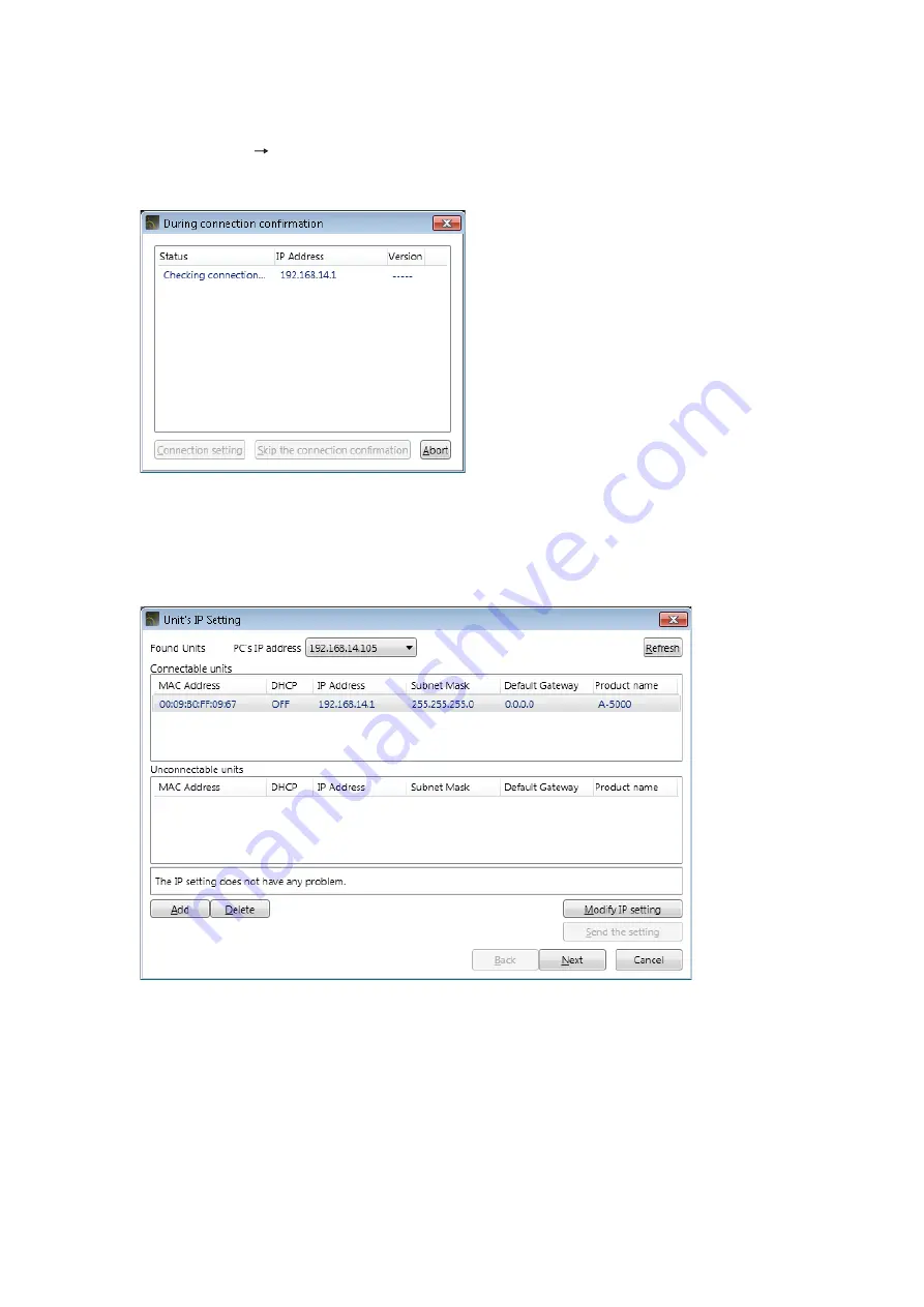
Connect to the unit displayed “Connectable units” field in the Unit’s IP setting screen.

 Step 1. Select [Network Connect] from the menu.

While the screen below is displayed, the target unit designated with the connection settings are being 

detected.

Note

If no units on the network have been set for the connection settings, the Unit’s IP Setting screen is 

displayed.

Perform network settings in the same manner as in the steps o

p. 34

“Connection Settings.”

On completion of network settings, the units listed in “Connectable units” field start being connected.

Содержание A-5000 Series

Страница 1: ...e INSTRUCTIONS Mixer amplifier A 5000 series Thank you for purchasing TOA s Mixer Amplifier Please carefully follow the instructions in this manual to ensure long trouble free use of your equipment Ve...

Страница 2: ...ible in online mode 20 9 SIGNAL PROCESSING DETAILED SETTINGS 21 9 1 Basic Function Box Operation in Flow View 21 9 2 Compression Settings 22 9 3 Manual Mute Settings 23 9 4 Master Volume Settings 26 9...

Страница 3: ...3 System Function 40 12 4 Communication Related Terms 40 12 5 External Control Functions 40 12 6 Maintenance Function 40 13 SPECIFICATIONS 41 13 1 Software Specification 41 13 2 Setting Display Items...

Страница 4: ...owing specifications 1 2 1 Recommended PC requirements Hardware Requirements CPU Intel CoreTM i3 2 GHz or faster Memory Over 2 GB Display 1024 x 768 resolution or higher Free Hard Disk Space Over 16 M...

Страница 5: ...ices connected to the same network The unit that communicates with this software can be detected using the Device detection function The Device detection function detects the unit connected on the loc...

Страница 6: ...er The English folder Japanese folder and other contents are displayed Step 3 Open the English folder Step 4 Open the Software folder Step 5 Double click the setup exe The window at right is displayed...

Страница 7: ...is not installed in the PC follow the on screen instructions to install it Connection to the internet is required Step 10 Click the Close button after installation completion The shortcut icon for the...

Страница 8: ...l name Preset memory name Primary reference preset memory number IP address Subnet mask Default gateway DHCP Compressor Mute Master volume PEQ Compressor Mute Master volume Use the Menu View to store...

Страница 9: ...art Menu You can start the A 5000 PC Software from the start menu Click the Start button on the PC s desktop and select Programs TOA Digital Audio Control A 5000 PC Software to start 4 2 Starting from...

Страница 10: ...e New File Open and Connect depending on the type of work to be done 1 File New Select this key to create a new setting file Clicking this key switches the screen display to the main screen see p 13 2...

Страница 11: ...Step 3 Select the desired unit from among the Controllable units and click the Finish button When the desired unit from which to receive data is not displayed The unit is not displayed in the above s...

Страница 12: ...ips Reception status is displayed in the Communication screen See p 40 Preset Static The display reverts to the initial operation selection screen if the Cancel button is clicked Step 4 Click the Comp...

Страница 13: ...MAIN SCREEN AND INDIVIDUAL VIEWS After initial operation selection settings the Main screen is displayed The main screen consists of the Menu View Status View and Flow View Menu View Status View Flow...

Страница 14: ...the value set for the function box selected on the flow view see p 17 to the clipboard Paste Pastes the data in clipboard to the function box selected on the flow view Clear Initializes the value set...

Страница 15: ...selected Preset Memory see p 29 Click this button to display the Memory List panel 3 Store button If this button is clicked the contents set in the Flow View can be written to the currently selected...

Страница 16: ...inal status Displays the manual mute terminal status Open Close muted 3 Impedance setting status status of DIP SW4 on the unit s rear panel Displays the impedance setting status High impedance 100 V l...

Страница 17: ...frequency characteristics curve set with the PEQ Frequency characteristics are indicated by a flat straight line when all gains are set to 0 dB For details see p 27 4 Compressor These function boxes a...

Страница 18: ...panel 7 Remote master volume control only displayed when in online mode Displays the gain value of the remote master volume output 8 Master volume control Allows operation of the master volume fader T...

Страница 19: ...nit Name Setting screen is displayed Step 2 Click a name box to enter a name Each name must be within 20 characters in length Step 3 Click the OK button The name is set and reflected in both Unit View...

Страница 20: ...g to the clicked box is displayed surrounded by a blue frame Click the Level Meter box The level meter displays signal levels in a bar graph Set the unit for operation within a level range that is not...

Страница 21: ...menu displayed by right clicking the box Data can be copied and pasted by dragging and dropping the box Copy Copies the parameters set for the function box selected on the operation view to the clipbo...

Страница 22: ...the Settings dialog box Settings are performed by either directly entering values or selecting given values 1 Threshold Sets the threshold value Compression is performed on input signals that have a...

Страница 23: ...ss between the unit and PC the input and output signal levels reduction level effective degree of compression and threshold level are displayed in the bar graph as shown below The reduction level atte...

Страница 24: ...he Mute activation trigger If Mode is set to Manual The indication Mute contact is displayed The contact input to the unit s rear panel mounted Manual Mute terminals is a mute trigger If Mode is set t...

Страница 25: ...be muted Multiple inputs can be selected Step 3 Click the input button for which detailed parameters are set The detailed settings for the clicked input are displayed graphically Step 4 Set the reduc...

Страница 26: ...he Master Volume is displayed 1 Gain display Displays the Master Volume gain Clicking the Gain display opens the dialog box for gain entry 2 Fader Used to set the Master Volume gain The fader knob is...

Страница 27: ...e initialized by selecting the Point Clear from the menu displayed when you right click on the filter point on a graph 3 Frequency control Sets each filter point s frequency Frequency Settings dialog...

Страница 28: ...requency and gain settings If Freq Low at left is clicked the indication changes and the frequency settings resolution is set to High Clicking the same button again restores the previous display and s...

Страница 29: ...lume Up to 16 preset memories can be stored The initial preset memory number that is called up when the power is switched on can also be set It is also possible to call up a different preset memory nu...

Страница 30: ...called up when the unit s power is switched on Step 1 Select Config Preset Memory Setting in the Menu View The Preset Memory Setting screen is displayed Step 2 Click the button for the desired preset...

Страница 31: ...reset memory number name button in the Memory View Memory List panel is displayed Memory List panel The currently selected Preset Memory button is displayed in orange Step 2 Click the desired preset m...

Страница 32: ...reset memory number Step 1 Click the preset memory number name button in the Memory View Memory List panel is displayed Memory List panel Stored in the preset memory number shown here The currently se...

Страница 33: ...fore the edit are called up 1 11 Communication settings 11 1 Connections between the PC and the Unit Connect the unit s LAN terminal to the PC via a switching hub Connect a PC and the unit to a switch...

Страница 34: ...ging the PC s network settings change them from the Windows Control Panel PC network setting cannot be changed using the A 5000 PC software When connecting to the unit via a router network settings ar...

Страница 35: ...transmits the IP settings to the corresponding unit and network setting for the unit is changed Step 4 Add the unit to be connected via a router in a list Clicking the Add button displays the Add tar...

Страница 36: ...unit from the list Select the unit to be deleted then click the Delete button The selected unit is deleted from the list Step 8 Update the firmware Select the unit from the Uncontrollable units list...

Страница 37: ...ayed the target unit designated with the connection settings are being detected Note If no units on the network have been set for the connection settings the Unit s IP Setting screen is displayed Perf...

Страница 38: ...he transfer direction PC Unit or Unit PC and click the Update button Then all unmatched setting data is simultaneously transferred in the designated direction Set contents of preset memory Nos 1 16 an...

Страница 39: ...ion Compresses the difference between the maximum sound output and minimum sound output This function can be set for Inputs 1 and 2 Threshold Level Compression Ratio Attack Time Release Time and Gain...

Страница 40: ...that the PC and target A 5000 series unit are communicating with each other When in online mode is a state that the A 5000 series unit is in online state 12 4 2 Offline state A state that the PC and t...

Страница 41: ...ing Storable in Preset Memory Channel Name 20 alphanumeric characters Example Mono In 1 Mono Out 1 13 2 3 Signal processing box PEQ Setting Item Setting Range Default Setting Remarks Online Setting St...

Страница 42: ...y Item Setting Range Default Setting Remarks Online Setting Storable in Preset Memory Mute operation status Mute enabled disabled Manual Mute terminal status Open close Unit s Manual Mute terminal sta...

Отзывы: