CHAPTER 1: Installation Cont.
Installation parts list
Trim removal tool
Flex claw tool
Flashlight
Zip ties
Wire strippers
16g plug connectors
16g ring connectors
Add-a-fuse (optional)
Heat shrink (assorted sizes)
3M mounting tape
Bubble level
Pre-planning
Determine best location for CPU Controller, parking sensors and wire routing
Tip: It’s a good idea to label the connector locations on the parking sensor wires at
both the connector end and the sensor head to help with troubleshooting should
there be any performance problems down the road.
The following is a loose guideline for hard wiring the TMG
Installation
1. Park on level ground
2. Shut off vehicle
3. Disconnect negative battery terminal.
4. Remove trim pieces for access to wiring passages.
5. Run sensor wires from the mounting location to the CPU controller. (Be sure to
keep wires secured in the engine bay and away from moving parts).
6. Access to passages through the fire wall can be achieved by piggy backing on an
existing wire route.
7. Use flex claw tool to pull wires through the firewall and into the cabin.
8. Any extra length of sensor wire should be coiled loosely and secured with a zip
tie to the vehicle, under the dash or behind the glove compartment.
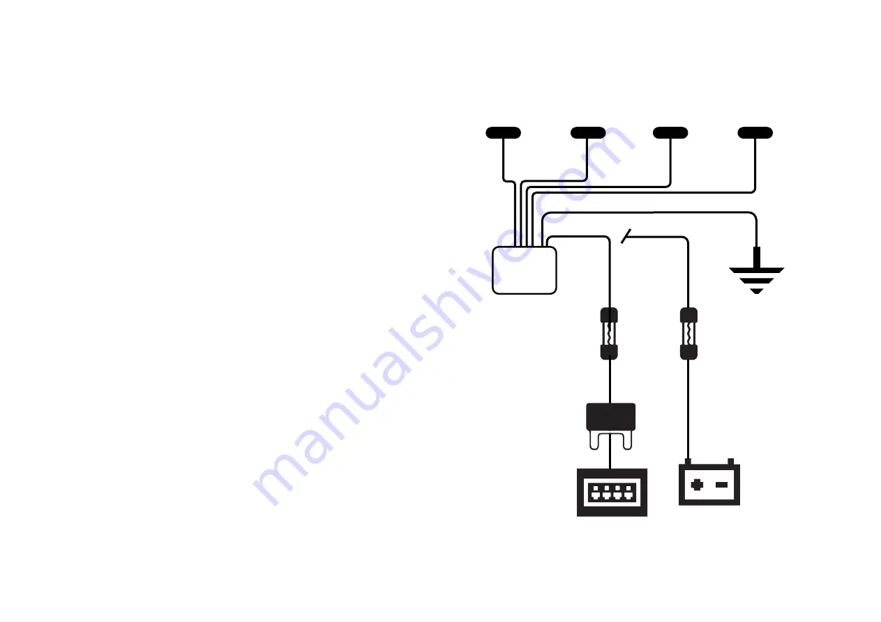
9. Wire the power to either the positive battery terminal or a switchable fuse in
the fuse box with an “add-a-fuse”. (Be sure to procure the right size add-a-fuse
for your fuse bank.)
10. Find a solid part of the vehicle’s frame that’s in a discreet location, drill a small
hole then connect the ground wire to the frame with a loop connector and an
appropriately sized machine screw.
11. Mount CPU controller in the cabin in an area where it can be accessed directly.
12. Connect negative battery terminal
13. Start the vehicle
CHAPTER 1: Installation Cont.
Sensors
Ground wire
Power wire
Power
Option 1
Power
Option 2
In-line
Fuse
In-line
Fuse
CPU
Controller
Negative
Vehicle Ground
Vehicle Fuse Box
Positive Battery
Terminal
ADD
A-FUSE
6
7


