background image

1. Before installation, be sure to remove all protective seals.

2. The trap can be installed either horizontally or vertically, but make sure the arrow on the trap 

points in the direction of flow.

3. Before installing the trap, blow out the inlet piping to remove all dirt and oil.

4. Install the trap in the lowest part of the pipeline or equipment so the condensate flows naturally 

into the trap by gravity. The inlet pipe should be as short and have as few bends as possible.

5. Support the pipes properly within 800 mm (2.5 ft) on either side of the trap.

6. Install a bypass valve to discharge condensate, and inlet and outlet valves to isolate the trap in 

the event of trap failure or when performing maintenance. 

7. Install a check valve at the trap outlet whenever the condensate discharge pipe leads to a tank 

or recovery line, or whenever the condensate collection pipeline is connected with more than 

one trap.

8. In order to avoid excessive back pressure, make sure the discharge pipes are large enough (the 

outlet back pressure should be no more than 80% of the inlet steam pressure).

9. The use of unions is recommended to facilitate connection and disconnection of the screwed 

version.

5. Proper Installation

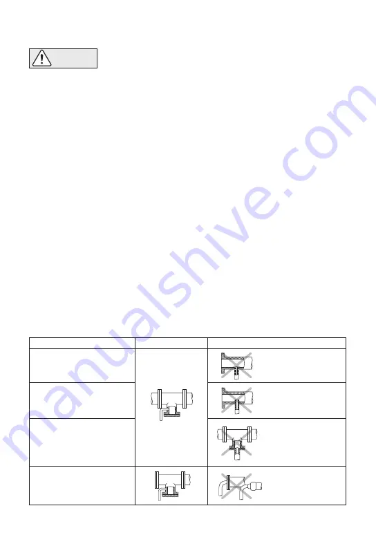
6. Piping Arrangement

Requirement

Diameter is too small.

Diameter is too small 
and inlet protrudes 
into pipe.

Rust and scale flow 
into the trap with the 
condensate.

Condensate collects 
in the pipe.

Correct

Incorrect

Install a catchpot of the 
proper diameter.

Make sure the flow of 
condensate is not 
obstructed.

To prevent rust and scale 
from flowing into the trap, 
connect the inlet pipe  25 - 
50 mm (1 - 2 in) above the 
base of the T - pipe.

When installing on the blind 
end, make sure nothing 
obstructs the flow of 
condensate.

• Installation, inspection, maintenance, repairs, disassembly, adjustment 

and valve opening/closing should be carried out only by trained 

maintenance personnel. 

• Take measures to prevent people from coming into direct contact with 

product outlets.

• Install for use under conditions in which no freeze-up will occur.

• Install for use under conditions in which no water hammer will occur.

CAUTION

Check to make sure that the pipes connected to the trap have been installed properly.

1. Is the pipe diameter suitable, and has sufficient space been secured for maintenance?

2. Has the trap been installed with the arrow on the body pointing in the direction of flow?

3. Have maintenance valves been installed at the inlet and outlet? If the outlet is subject to 

back pressure, has a check valve been installed?

4. Is the inlet pipe as short as possible, with as few bends as possible, and installed so that the 

condensate will flow naturally down into the trap?

5. Has the piping work been done correctly, as shown in the table below?

̶ 5 ̶

Содержание ThermoDyne A3N-AF3N

Страница 1: ...N MANUAL Keep this manual in a safe place for future reference MODEL A3N AF3N Copyright C 2018 by TLV CO LTD All rights reserved 881 Nagasuna Noguchi Kakogawa Hyogo 675 8511 Japan Manufacturer Tel 81 0 79 422 1122 Fax 81 0 79 422 0112 Option BD2 ...

Страница 2: ...ommended operating pressure temperature and other specification ranges Improper use may result in such hazards as damage to the product or malfunctions which may lead to serious accidents Local regulations may restrict the use of this product to below the conditions quoted Take measures to prevent people from coming into direct contact with product outlets Failure to do so may result in burns or o...

Страница 3: ...which no water hammer will occur The impact of water hammer may damage the product leading to fluid discharge which may cause burns or other injury 2 Specifications To avoid malfunctions product damage accidents or serious injury install properly and DO NOT use this product outside the specification range Local regulations may restrict the use of this product to below the conditions quoted CAUTION...

Страница 4: ...Maintenance Kit R Repair Kit Integral part of Inner Cover Integral part of Module Valve Seat Description No 1 2 3 4 5 6 7 8 9 10 11 12 13 14 15 16 17 Body Outer Cover Gasket Inner Cover Gasket Outer Module Gasket Inner Module Gasket Module Valve Seat Disc Inner Cover Air Vent Ring Module Pin Outer Cover Screen Screen Holder Gasket Screen Holder Disc Holder Ring Cover Bolt Nameplate M R 3 ...

Страница 5: ...Outer Cover Outer Cover Cover Bolt Inner Cover Screen Holder 32 50 mm 1 2 15 25 mm 1 Part 1 2 1 4 1 2 5 8 1 8 15 16 13 16 13 16 N m 50 400 300 lbf ft 37 290 220 lbf ft 160 160 59 in 2 2 in 2 1 1 N m 220 220 80 mm 16 75 54 mm 71 46 38 Tightening Torque and Distance Across Flats 1 N m 10 kg cm If drawings or other special documentation were supplied for the product any torque given there takes prece...

Страница 6: ...meter is too small and inlet protrudes into pipe Rust and scale flow into the trap with the condensate Condensate collects in the pipe Correct Incorrect Install a catchpot of the proper diameter Make sure the flow of condensate is not obstructed To prevent rust and scale from flowing into the trap connect the inlet pipe 25 50 mm 1 2 in above the base of the T pipe When installing on the blind end ...

Страница 7: ...properly Steam is discharged from the trap in short rapid bursts 8 Inspection and Maintenance Installation inspection maintenance repairs disassembly adjustment and valve opening closing should be carried out only by trained maintenance personnel Before attempting to open the trap close the inlet and outlet isolating valves and wait until the trap has cooled completely Failure to do so may result ...

Страница 8: ...ve gasket only if worn or damaged Remove with a socket wrench Do not remove Remove being careful not to scratch the lapped surface Remove without bending Remove without bending as it will not return to its proper shape Remove being careful not to scratch the lapped surface Remove with pliers Do not remove Do not remove Remove with a socket wrench Remove gasket and clean sealing surfaces Remove gas...

Страница 9: ...10 Optional Blowdown Valve BD2 Coat with Anti Seize Screen Holder Troubleshooting continued BD2 BD2 Clean or replace screen Replace worn parts Replace air vent ring or disc holder ring Air vent ring bimetal or disc holder ring is broken and obstructing valve closure Valve closure is obstructed by scale etc Disc or valve seat is worn For BD2 15 25 mm 1 For BD2 and Screen Holder 32 50 mm 2 2 1 4 1 1...

Страница 10: ...22 lbf ft and confirm that there is no leakage If leakage continues dirt or scale may prevent the valve from sealing Open and blow out again then try to close once more 32 21 Note Do not leave the vicinity while the blowdown valve is in the open position CAUTION Always wear eye protection and heat resistant gloves when operating the blowdown valve Failure to do so may result in burns or other inju...

Страница 11: ...SHIPMENT BY TLV Exclusive Remedy THE EXCLUSIVE REMEDY UNDER THIS WARRANTY UNDER ANY EXPRESS WARRANTY OR UNDER ANY IMPLIED WARRANTIES NOT NEGATED HEREBY INCLUDING THE IMPLIED WARRANTIES OF MERCHANTABILITY AND FITNESS FOR A PARTICULAR PURPOSE IS REPLACEMENT PROVIDED a THE CLAIMED DEFECT IS REPORTED TO TLV IN WRITING WITHIN THE APPLICABLE WARRANTY PERIOD INCLUDING A DETAILED WRITTEN DESCRIPTION OF TH...

Страница 12: ...HANTABILITY AND FITNESS FOR A PARTICULAR PURPOSE CANNOT BE EXCLUDED SUCH DAMAGES ARE EXPRESSLY LIMITED IN AMOUNT TO THE PURCHASE PRICE OF THE DEFECTIVE PRODUCT THIS EXCLUSION OF CONSEQUENTIAL AND INCIDENTAL DAMAGES AND THE PROVISION OF THIS WARRANTY LIMITING REMEDIES HEREUNDER TO REPLACEMENT ARE INDEPENDENT PROVISIONS AND ANY DETERMINATION THAT THE LIMITATION OF REMEDIES FAILS OF ITS ESSENTIAL PUR...

Отзывы: