81 29 2 208 034
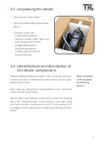
Granule jet blasting device
PG 5–8
Owner‘s Manual
Translation of the original instructions
Страница 1: ...81 29 2 208 034 Granule jet blasting device PG 5 8 Owner s Manual Translation of the original instructions...
Страница 2: ...he strict limitations of copy right legislation without the consent of the manufacturer is permitted this rendering the offen der liable to criminal prosecution This applies likewise for the extractio...
Страница 3: ...blasting device 15 2 Granule jet blasting device preparation and connection 16 3 Filling with blasting material 18 4 Connect vacuum adapter to vacuum cleaner 22 5 Attach blasting lance to handle 23 6...
Страница 4: ...ct improvements without prior notification Read the instruction manual carefully before using the device All handling necessary to ensure correct operation is descri bed in the instruction manual No w...
Страница 5: ...neral instructions Observe the general instructions Wear face mask Wear hearing protection Wear gloves Wear protective clothing Warning General source of danger Warning System under pressure Risk of h...
Страница 6: ...be operated in combination with the vacuum adapters that are approved for the relevant engine type and a vacuum cleaner with sufficient suction po wer Unauthorised modifications or changes to the devi...
Страница 7: ...mask and safety shoes Risk of injury Before carrying out maintenance or cleaning work and always before filling the device with granules the com pressed air supply must be disconnected and the device...
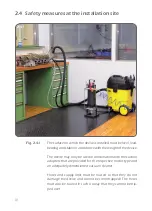
Страница 8: ...depressurised Item B work item Item A relieve Fig 2 3 1 Fig 2 3 2 If a control function fails the device must be taken out of service immediately and repaired by a trained expert There is a pressure...
Страница 9: ...trol function fails If the ball valve is closed no air or other blasting material can exit from the lance If the safety equipment malfunctions the device must be taken out of service immediately The d...
Страница 10: ...of the device The device may only be used in combination with the suction adapters that are provided for the respective motor type and an adequately dimensioned vacuum cleaner Hoses and supply lines m...
Страница 11: ...y ball valve gra nule control valve compressed air control valve pressure gau ge and safety valve Hose package with granule transportation hose and three colour coded control hoses Handle with 2 way b...
Страница 12: ...32 38 31 34 21 20 9 22 24 49 18 25 37 27 7 28 7 12 42 46 43 47 45 48 15 26 19 3 1 13 2 17 6 33 44 41 40 39 51 50 30 5 35 10 11 49 18 14 15 36 16 4 17 23 29 8 3 3 1 12 3 3 Device components...
Страница 13: ...Elbow fitting 26 Screw in fitting 27 Straight male connector 28 Double nipple No Title 29 Elbow fitting connection 30 Disc 31 Hose black 6 mm 32 Hose blue 6 mm 33 Hose transparent 6 mm 34 Nozzle bent...
Страница 14: ...0 mm Max operating pressure 8 bar Container volume 5 l Weight 15 5 kg Hose package working length 4 m Length and weight without hoses 1 Control air transparent hose 2 Main air black hose 3 Granules su...
Страница 15: ...device to the compressed air supply Start the cleaning process Blasting with air blowing out Blasting with air granule mixture cleaning Cleaning the inlet valves and the inlet channel Taking device ou...
Страница 16: ...actory without a compressed air coupling The ball valve has a connecting thread with a female thread of G The thread is fitted with a closing cap Insert a suitable compressed air connection with seal...
Страница 17: ...sed air The granule jet blasting device may only be operated with an external supply unit with variable operating pressure The operating pressure of the device should be bet ween 6 and 8 bar and may n...
Страница 18: ...ball valve in Relieve position Fig 4 3 2 Pressure gauge must not be indicating any pressure Fig 4 3 3 Undo eye bolts and swivel out swivel ling screw fitting Attention Device may only be filled if con...
Страница 19: ...pproved by the manufacturer may be used Cleaning granulate The blasting material must be free of impurities Never re use blasting material Fig 4 3 4 Remove lid of container Fig 4 3 5 Filling with gran...
Страница 20: ...the device the working process must be interrupted and the cause thereof remedied Check lid seal Seal must be clean and must not be damaged Place lid on container Fit swivelling screw fitting Tighten...
Страница 21: ...4 3 10 4 3 9 4 3 1 1 21...
Страница 22: ...stepped grommet Fig 4 4 3 Secure suction hose with a hose clamp Fig 4 4 4 Fix suction adapter in the inlet channel of the cylinder head The correct adapter for the respec tive cylinder head must be u...
Страница 23: ...suitable blasting lance to 2 way ball valve Fig 4 5 2 Move 2 way ball valve to the open position Fig 4 5 3 Slowly turn 3 way ball valve to the wor king position Fig 4 5 4 No air must come out of the...
Страница 24: ...2 4 6 1 24 4 6 Starting the cleaning process Before the cleaning process is started the operator must put on the prescri bed protective clothing Only trained and instructed experts may operate the dev...
Страница 25: ...ion is used to blow out the cleaning area Fig 4 7 2 Blasting with air granule mixture cleaning When the pull off lever is moved to position 2 pushed all the way air and granules flow out of the blasti...
Страница 26: ...th air Repeat changeover between cleaning and blowing out several times Each time the blasting lance must be moved to a different position so that the entire carbonised area is cleaned No blasting mat...
Страница 27: ...e clea ning result must be visually inspected If the result is unsatisfac tory the process must be repeated and or the working pressu re of the device increased Max 8 bar The inlet valves and the inle...
Страница 28: ...the Relieve position Fig 4 9 2 The compressed air supply line can be disconnected if no pressure is being indi cated on the pressure gauge Fig 4 9 3 Remove cover of blasting device and re move remaind...
Страница 29: ...during operation and must be checked for damage at least every two months The blasting material hose should be replaced once per annum if the device is used regularly Fig 5 1 1 Remove hose with protec...
Страница 30: ...opportunity must be taken to check all hose grommets and connecting nipp les on the control valve and the handle If the size of the hole has been incre ased significantly by the flow of bla sting mate...
Страница 31: ...must be clea ned Fig 5 1 10 Unscrew all filter inserts and blow them out with a compressed air blow out gun from threaded side until all granule or dust residue has been removed After cleaning the fi...
Страница 32: ...19 16 22 8 6 1 30 23 24 26 11 21 15 17 3 29 25 12 15 21 20 14 7 28 10 5 27 4 9 13 7 21 21 9 2 9 18 32 32 5 2 Spare parts and accessories for the PG 5 8 granule jet blasting device...
Страница 33: ...uble nipple 14 SER GPG 00000141 Screw in fitting 15 SER GPG 00000142 Screw in fitting 16 SER GPG 00000143 Press nipple M 16x1 5 17 SER GPG 00000144 Threaded nozzle 1 4 thread 18 SER GPG 00000052 O rin...
Страница 34: ...lidated if the operating instructions are not followed and the maintenance work has not be carried out as stipulated 4 The warranty is invalidated if the device is used incorrectly and or the permitte...
Страница 35: ...een developed and designed in accordance with the standards and guidelines of TKR Spezialwerkzeuge GmbH Am Waldesrand 9 11 58285 Gevelsberg Germany Serial number range 00001 10000 Referenced German Pr...
Страница 36: ...Am Waldesrand 9 11 D 58285 Gevelsberg Germany Phone 49 2332 66607 0 Fax 49 2332 66607 941 E mail info tkrgroup com Internet www tkrgroup com PSD BED 00000037 R5 19 03 V1...