background image

Pressure Switch Replacement

See Figure 7

WARNING:

Before proceeding, follow the Pressure

Relief Procedure outlined on page 5.  Additionally, follow
all other warnings to reduce the risk of an injection
injury, injury from moving parts or electric shock.  
1. Remove socket head cap screws.
2. Remove electrical cover plate #60, located near pressure 

switch and disconnect two red wires from clutch starter 
#58. See pg. 20.

3. Remove screw #27 from pressure switch adjustment 

knob and slide knob off.

4. Remove screw #27 located on side of gear box housing 

#53 and using a 1/8" allen wrench remove set screw 
#56, until pressure switch #231 is able to slide down 
through. Feed electrical wires down at the same time.

5. Insert new switch assembly #231). See Figure 8, p. 22)

into housing while carefully working the wires into the 
switch box.  Using needle nose pliers, reconnect wires 
to motor starter.

6. Making sure that the switch assembly is fully inserted, 

tighten set screw #56 with a 1/8" allen wrench until the 
switch assembly is secure.  Reattach adjustment knob 
#26. See pg. 20.

7. Inspect O-Rings #232 and #233 on switch assembly.
8. Install insulator plate #66 and plate #60. See pg. 20. 
9. The pressure switch is factory calibrated so no 

adjustment is required.

Service/Replacement of the
Pressure Relief Prime Valve

WARNING:

Before proceeding, follow the Pressure Relief

Procedure outlined on Page 5.  Additionally, follow all
other warnings to reduce the risk of an injection injury,
injury from moving parts or electric shock.  
1. Remove the Dowel Pin (#226) from Bypass Valve Handle

(#227).

2. Remove Handle (#227) and Bypass Cam (#225).
3. Using a wrench, loosen Bypass Housing (#218) and

unscrew.

4. Unscrew Bypass Retainer (#224) and remove Bypass Valve

Stem (#220).

5. Inspect ball on end of Stem (#220) and O-Ring (#219). Clean

or replace if worn.

6. Screw completed assembly into Filter Block (#207). Tighten

securely with wrench.

7. Install  Bypass Cam (#225) over Bypass Retainer (#224),

lubricate with grease.  Line up Dowel Pin (#226) on Cam
(#227) with hole on Filter Block (#207).

8. Using Dowel Pin (#226) line up Stem (#220) with hole on

Handle (#227). Secure Handle with Dowel Pin (#226).

9. IMPORTANT: If Handle (#227) rotates 360° check Pin on

Cam (#225).

Service / Replacement 
of Filter

WARNING:

Before proceeding, follow the Pressure Relief

Procedure outlined on Page 5.  Additionally, follow all
other warnings to reduce the risk of an injection injury,
injury from moving parts or electric shock.  

PUMP FILTER
1. Unscrew Filter Housing (#202).
2. Remove Filter Cartridge (#204).  Clean or replace.
3. Inspect O-Ring (#206).  Clean or replace.
4. Reattach Filter Housing (#202).

Gun Filter

WARNING:

Follow all safety precautions as described in

high pressure warning section before proceeding.  If your
spray gun leaks or spits at the tip when you release the
trigger, the needle or seat is dirty, worn or damaged and
must be cleaned or replaced.
Replacement or Removal of Filter:
1. First pull down on trigger safety guard and swing away from

handle.

2. Unscrew handle from spray head.
3. Unscrew left hand threaded* filter from spray head. (*NOTE:

Left handed thread requires turning the filter clockwise to
remove.)

4. Screw new or cleaned filter into the head. (To reinstall left

hand thread turn counterclockwise.)

5. Reattach handle to head and secure safety trigger guard.

(NOTE: If filter breaks off in the head use a small wood
screw to remove.)

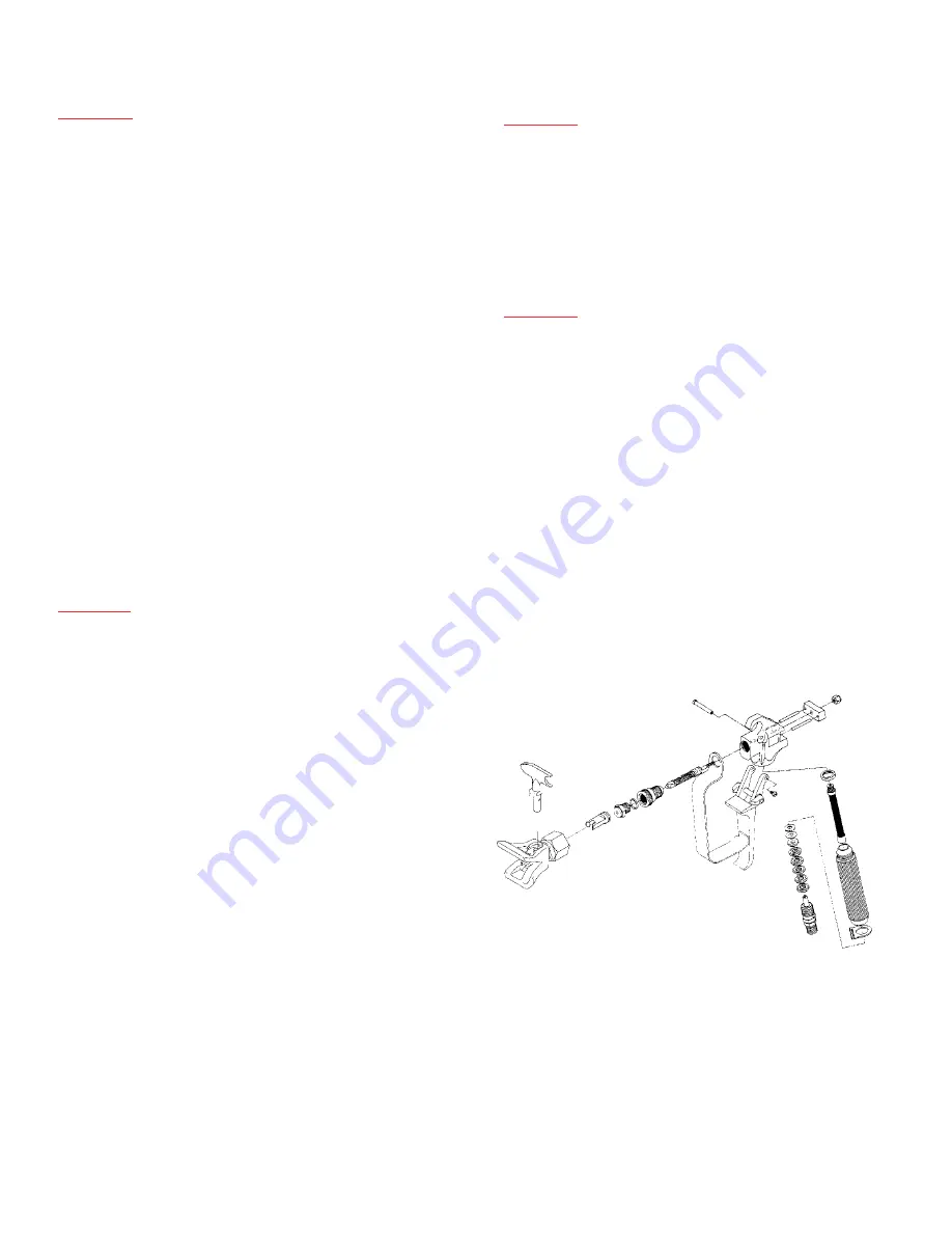
Figure 9 For more detail, part number information and assembly
drawings at larger scale, please see the LX-80 Professional
Airless Gun Owner’s Manual (#313-012).

23

Содержание 755-095

Страница 1: ...095 LowRiderComplete 755 100 HighRiderPumpOnly 755 101 HighRiderComplete 755 102 This manual contains important warnings and instructions Please read and retain for reference Never operate this unit...

Страница 2: ...ion 15 25 Frame 15 Replacement Labels 16 Engine 18 Maintenance 19 Gear Box 20 Clutch Rotor Gear Repair 21 On Off Switch 21 Filter Block 22 Pressure Switch 23 Prime Relief Valve 23 Filter Replacement 2...

Страница 3: ...properly review the repair procedure to determine if everything was done correctly Refer to the Troubleshooting Charts to help identify other possible problems 4 Make certain that the service area is...

Страница 4: ...intenance Schedule Check Piston Seal Lubricant Level WEEKLY EPIC 690HPG Change Engine Oil Every 50 Hours Date Date Date Date Date Date Date Date Date Date Clean Air Filter Daily It is extremely import...

Страница 5: ...forth can withstand the high pressures which develop NEVER exceed the pressure rating of any component in the system 6 WARNING The paint hose can develop leaks from wear kinking abuse etc A leak is c...

Страница 6: ...mentos accesorios est n en condiciones de tolerar las altas presiones que se presentan JAMAS exceda la clasificaci n de presi n de cualquier componente del sistema 6 ADVERTENCIA La manguera de pintura...

Страница 7: ...s flexibles accessoires raccords articulations etc sont bien capables de r sister aux hautes pressions pr vues Ne d passez JAMAIS la capacit de pression nominale d aucun composant du syst me DANGER Af...

Страница 8: ...itan Tool Inc spray equipment includes aluminum or galvanized components and will be affected by Halogenated Hydrocarbon solvents DO NOT USE HALOGENATED HYDROCARBONS IN TITAN EQUIPMENT EXPLANATION OF...

Страница 9: ...dangereux Des tincelles peuvent galement se produire lors de branchement ou d branchement d un cordon d alimentation lectrique ou lors de la mise en marche d un moteur au gaz De telles tincelles sont...

Страница 10: ...ogenados SOLVANTS HALOG N S D FINITION Tout solvant hydrocarbure contenant l un des l ments suivants EXEMPLES liste incomplete Pour d terminer si vos solvants ou rev tements contiennent des solvants a...

Страница 11: ...run itself dry Step 12 Check filter on pump and gun Clean or replace Step 13 Remove spray tip from solvent clean with a soft bristle brush and store in a dry place PROBABLE CAUSE 1 Inadequate fluid d...

Страница 12: ...ench 1 313 129 690 Label 1 313 176 Warning Label 1 WARNING Before proceeding follow the Pressure Relief Procedure outlined on Page 5 Additionally follow all other warnings to reduce the risk of an inj...

Страница 13: ...17 690HPG Figure 5 Syphon Down Tube for use with the High Rider Frame Only...

Страница 14: ...heck and fill the gas tank After the first 20 hours of operation Drain the oil and refill with clean oil Daily Check the engine oil level and fill as necessary Weekly Remove the cover of the air filte...

Страница 15: ...sk of an injection injury injury from moving parts or electric shock 1 Remove safety plate 70 from front of pump 2 Remove front cover 41 3 Remove 4 socket head screws 42 and slide pump housing assembl...

Страница 16: ...d unscrew 4 Unscrew Bypass Retainer 224 and remove Bypass Valve Stem 220 5 Inspect ball on end of Stem 220 and O Ring 219 Clean or replace if worn 6 Screw completed assembly into Filter Block 207 Tigh...

Страница 17: ...03 Packing Grease and 700 793 Piston Guide Tool also included 391 700 804 Gasket 1 392 490 109 Fitting 1 350 730 501 Fluid Section Complete 301 305 307 315 323 1 325 700 024 Optional Urethane O Ring 1...

Страница 18: ...tightly with a wrench PACKING REPLACEMENT 13 Unscrew hose 242 see Figure 8 p 22 from fitting 392 see Figure 10 p 24 14 Remove screws 306 with a 3 8 allen wrench and slide pump section down so that th...

Страница 19: ...n Site Gallons Sprayed Tips Used Date Completed Quantity Sizes Job Name Foreman s Name Type of Coating Date Begun Site Gallons Sprayed Tips Used Date Completed Quantity Sizes Job Name Foreman s Name T...

Страница 20: ...material being sprayed hose diameter and tip size DP 30 supplied with 25 of hose and a Profit Gun DP 30 0 3000 psi 017 w 1 gun 37 lbs 8 33 100 ft 703 095 703 100 1 2 HP totally enclosed AC motor 1100H...

Отзывы: