background image

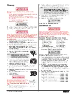
5. Turn on the sprayer by moving the ON/OFF switch to the

ON position. 

6. Allow the sprayer to run for 15–30 seconds to flush the old

solvent out through the return hose and into the metal
waste container.

7. Turn off the sprayer by moving the ON/OFF switch to the

OFF position.

8. Move the PRIME/SPRAY valve up to the

SPRAY position.

9. Turn on the sprayer.

10. Unlock the gun by turning the gun trigger

lock to the unlocked position.

Ground the gun by holding it against the
edge of the metal container while
flushing.  Failure to do so may lead to a
static electric discharge, which may cause
a fire.

11. Trigger the gun into the metal waste container until the old

solvent is gone and fresh solvent is coming out of the gun.

12. Lock the gun by turning the gun trigger

lock to the locked position.

13. Set down the gun and increase the

pressure by turning the pressure control
knob slowly clockwise into the green zone.

14. Check the entire system for leaks.  If

leaks occur, follow the “Pressure Relief
Procedure” in this manual before
tightening any fittings or hoses.

15. Follow the “Pressure Relief Procedure” in this manual

before changing from solvent to paint.

Be sure to follow the pressure relief procedure when
shutting the unit down for any purpose, including
servicing or adjusting any part of the spray system,
changing or cleaning spray tips, or preparing for cleanup.

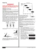
Painting

1. Place the siphon tube into a container of paint.
2. Place the return hose into a metal waste

container.

3. Set the pressure to minimum by turning

the pressure control knob to the “Min”
setting in the yellow zone.

4. Move the PRIME/SPRAY valve down to the

PRIME position.

5. Turn on the sprayer by moving the ON/OFF

switch to the ON position.

6. Allow the sprayer to run until paint is

coming through the return hose into the metal waste
container.

7. Turn off the sprayer by moving the ON/OFF switch to the

OFF position.

8. Remove the return hose from the waste container and place

it in its operating position above the container of paint.

9. Move the PRIME/SPRAY valve up to the

SPRAY position.

10. Turn on the sprayer.

11. Unlock the gun by turning the gun trigger

lock to the unlocked position.

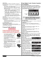
Min PSI 

(Bar)

Max PSI 

(Bar)

Pu

lse

Cl

ea

n

WARNING

Trigger lock in  

locked position.

WARNING

NOTE: Make sure that the spray gun does not have a

tip or tip guard installed.

Ground the gun by holding it against the
edge of the metal container while flushing.
Failure to do so may lead to a static
electric discharge, which may cause a fire.

12. Trigger the gun into the metal waste

container until all air and solvent is flushed from the spray
hose and paint is flowing freely. from the gun.

13. Lock the gun by turning the gun trigger

lock to the locked position.

14. Turn off the sprayer.
15. Attach tip guard and tip to the gun as

instructed by the tip guard or tip manuals.

POSSIBLE INJECTION HAZARD.  Do not spray without the
tip guard in place.  Never trigger the gun unless the tip is in
either the spray or the unclog position.  Always engage the
gun trigger lock before removing, replacing or cleaning tip.

16. Turn on the sprayer.
17. Increase the pressure by turning the pressure control knob

slowly clockwise toward the green zone and test the spray
pattern on a piece of cardboard.  Adjust the pressure control
knob until the spray from the gun is completely atomized.
Try to keep the pressure control knob at the lowest setting
that maintains good atomization.

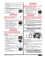
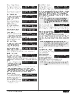
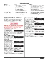
Control Panel Indicators

The following is a description of the control panel indicators.

Pressure Indicator

The pressure indicator shows the current operating pressure of
the sprayer.  It has three different indications:  blinking yellow,
solid yellow, and solid green.

Blinking Yellow

When the pressure indicator is blinking yellow, the sprayer is
operating between 0 and 200 PSI.  A blinking yellow pressure
indicator means:

• The sprayer is plugged in and turned “ON”
• The sprayer is at priming pressure (little or no pressure)
• It is safe to move the PRIME/SPRAY valve between

positions

• It is safe to change or replace the spray tip

NOTE: If the pressure indicator begins blinking yellow

when the pressure control knob is set at a
higher pressure and the PRIME/SPRAY valve is
in the SPRAY position, either the spray tip is
worn or the sprayer is in need of service/repair.

Min PSI 

(Bar)

Max PSI 

(Bar)

Blinking Yellow

0-200 PSI

Solid Yellow

201-1900 PSI

Solid Green 

1901-3300 PSI

Motor  Running

Pu

lse

Cl

ea

n

Pressure 

Indicator

Motor Running 

Indicator

NOTE: If the sprayer is equipped with an Xact Digital

Control System, go to “Xact Digital Control
System Operation” at the end of the Operation
section of this Manual.

NOTE: Turning the pressure up higher then needed to

atomize the paint will cause premature tip wear
and additional overspray.

WARNING

Trigger lock in  

locked position.

WARNING

© Titan Tool Inc.  All rights reserved.

5

Содержание 540ix

Страница 1: ...ore reading this manual 540ix Airless Sprayer Owner s Manual For professional use only NOTE This manual contains important warnings and instructions Please read and retain for reference X Lock Theft Deterrent System Security Code Serial _ _ _ _ _ _ _ _ _ _ Model Numbers Skid Basic 700 129 High Rider Basic 700 134 ...

Страница 2: ...olvent flowing through the equipment is able to result in static electricity Static electricity creates a risk of fire or explosion in the presence of paint or solvent fumes All parts of the spray system including the pump hose assembly spray gun and objects in and around the spray area shall be properly grounded to protect against static discharge and sparks Use only conductive or grounded high p...

Страница 3: ...state and national codes governing ventilation fire prevention and operation 11 The United States Government Safety Standards have been adopted under the Occupational Safety and Health Act OSHA These standards particularly part 1910 of the General Standards and part 1926 of the Construction Standards should be consulted WARNING 12 Before each use check all hoses for cuts leaks abrasion or bulging ...

Страница 4: ...f this sprayer is new it is shipped with test fluid in the fluid section to prevent corrosion during shipment and storage This fluid must be thoroughly cleaned out of the system with mineral spirits before you begin spraying Always keep the trigger lock on the spray gun in the locked position while preparing the system 1 Place the siphon tube into a container of mineral spirits that has a flash po...

Страница 5: ...uard installed Ground the gun by holding it against the edge of the metal container while flushing Failure to do so may lead to a static electric discharge which may cause a fire 12 Trigger the gun into the metal waste container until all air and solvent is flushed from the spray hose and paint is flowing freely from the gun 13 Lock the gun by turning the gun trigger lock to the locked position 14...

Страница 6: ...l Control System Operation if equipped The Xact Digital Control System is an optional add on that increases the functionality of the sprayer It is installed directly below the pressure control knob on the control panel It consists of a display and four function keys The display shows various menu screens that allow the user to customize and monitor sprayer operation using the function keys Functio...

Страница 7: ... MENU UNIT SERIAL SELECT 4 MENU 1 JOB GALLONS XXXX MENU 1 RESET 3 JOB VOLUME SELECT 4 MENU 1 GALLONS XXXXXX PRESS 1 FOR MENU VOLUME PUMPED SELECT 4 MENU 1 Titan Tool Inc All rights reserved 7 Security Code Screen The Security Code screen allows the user to set a four digit security code to prevent unauthorized use of the sprayer If a security code has been set the control system display will ask f...

Страница 8: ...o as to lap the previous pattern by 50 Too Thick Offspray Arcing Gun at angle start stroke release trigger pull trigger end stroke WARNING 8 Titan Tool Inc All rights reserved For corners and edges split the center of the spray pattern on the corner or edge and spray vertically so that both adjoining sections receive approximately even amounts of paint When spraying with a shield hold it firmly ag...

Страница 9: ... moving the PRIME SPRAY valve to PRIME in case the sprayer is pressurized WARNING CAUTION WARNING 13 Continue to trigger the spray gun into the waste container until the solvent coming out of the gun is clean 14 Follow the Pressure Relief Procedure found in the Operation section of this manual 15 Unplug the unit and store in a clean dry area Do not store the unit under pressure Maintenance Before ...

Страница 10: ...t of the motor crankshaft that extends through the slider assembly 10 Titan Tool Inc All rights reserved Replacing the Gears 1 Perform the Pressure Relief Procedure and unplug the sprayer 2 Loosen and remove the four motor cover screws Remove the motor cover 3 At the electronic pressure control EPC on the back of the motor disconnect the wire coming from the potentiometer and the wire coming from ...

Страница 11: ...al 9 Using a wrench remove the transducer assembly from the pump block 10 Thread the new transducer assembly into the pump block Tighten securely with a wrench 11 Plug the new transducer wire into the transducer jumper refer to the electrical schematic in the Parts List section of this manual 12 Reassemble the pump by reversing steps 1 7 T Slot Pump Housing Pump Block Pump Block Mounting Screw Fro...

Страница 12: ...ring disassembly of the outlet valve Outlet Valve Retainer Outlet Valve Seat Outlet Valve Ball Outlet Cage Crush Washer Piston Rod Foot Valve Housing Foot Valve Seat Foot Valve Ball Bushing Teflon O Ring Inlet Cage Foot Valve Seal Pump Block WARNING 12 Titan Tool Inc All rights reserved 6 Reassemble the valves by reversing the steps above Repacking the Fluid Section 1 Remove the foot valve assembl...

Страница 13: ...filter housing 2 Turning clockwise unscrew the filter from the pump block 3 Inspect the seal Based on inspection clean or replace the seal 4 Turning counterclockwise thread the new or cleaned filter into the pump block 5 Slide the filter housing over the filter and thread it into the pump block until secure Pump Block Seal Filter Filter Housing NOTE Left handed threads require turning the filter c...

Страница 14: ... service center 1 Repack the pump following the Servicing the Fluid Section procedure in the Maintenance section of this manual 2 Replace the piston rod following the Servicing the Fluid Section procedure in the Maintenance section of this manual 1 Replace hose with a minimum of 50 of 1 4 grounded textile braid airless paint spray hose 2 Replace the spray tip following the instructions that came w...

Страница 15: ...er screen appears when the transducer has become disconnected or is defective Take the sprayer to a Titan authorized service center for repair Check Motor Screen E3 The Check Motor screen appears when the motor or motor sensor is defective Take the sprayer to a Titan authorized service center for repair Low Voltage Screen E4 The Low Voltage screen appears when the sprayer shuts down because of low...

Страница 16: ...tilisez pas de peinture ou de solvant contenant du halon par exemple le chlore les agents antimoisissure à l eau de Javel le chlorure de méthylène et le trichloroéthane Ils ne sont pas compatibles avec l aluminium Contactez le fournisseur de revêtements pour connaître la compatibilité du matériau avec l aluminium 8 La zone de pulvérisation doit toujours être bien aérée Une bonne quantité d air fra...

Страница 17: ...as le tuyau pour tirer ou soulever l équipement 9 Utilisez la plus basse pression possible pour rincer l équipement 10 Respectez tous les codes locaux étatiques et nationaux qui régulent la ventilation la prévention d incendies et le fonctionnement 11 Les normes de sécurité du gouvernement des États Unis ont été adoptées dans la loi Occupational safety and Health Act OSHA Ces normes en particulier...

Страница 18: ...VERTENCIA Español 8 Mantenga la zona de pulverización bien ventilada Asegúrese de que circula aire fresco por la zona para evitar que se acumulen vapores inflamables en el aire de la zona de pulverización Ponga el conjunto de la bomba en una zona bien ventilada No pulverice el conjunto de la bomba 9 No fume en la zona de pulverización 10 No encienda interruptores de luces motores ni productos simi...

Страница 19: ... las Normas sobre construcción 12 Cada vez que vaya a utilizar el equipo compruebe antes todas las mangueras en busca de cortes fugas abrasión o bultos en la cubierta Compruebe el movimiento de los acoplamientos y si están dañados Sustituya inmediatamente una manguera si descubre alguna de estas anomalías No repare nunca una manguera de pintura Sustitúyala por una manguera conductora a alta presió...

Страница 20: ...20 Titan Tool Inc All rights reserved Parts List Main Assembly 12 13 1 3 6 5 7 8 9 10 4 11 2 18 19 20 22 21 23 24 25 26 27 16 17 15 14 High Rider Model ...

Страница 21: ...skid 1 704 571 Fluid section assembly high rider 20 704 117 Socket screw 2 21 704 304 Pail hook high rider 1 22 763 552 Lock washer high rider 2 23 710 033 Hex screw high rider 2 24 702 239 Return hose high rider 1 25 755 225 Siphon tube high rider 1 26 730 334 Hose clip high rider 1 27 710 046 Inlet screen high rider 1 28 800 929 Fuse 15A not shown 1 Skid Assembly Item Part Description Quantity 1...

Страница 22: ...14 13 15 16 17 18 19 6 21 22 20 Install upper packing with raised lip and O ring facing down O Ring Raised Lip Install lower packing with the beveled edge facing up Beveled Edge NOTE When using hot solvents replace Viton valve stem o ring item 27 with optional Teflon valve stem o ring P N 700 897 Install using o ring replacement tool P N 700 890 ...

Страница 23: ...ing Viton 1 700 897 Valve stem o ring Teflon optional 28 221 012 O ring Viton 1 29 222 012 O ring Teflon 1 30 700 537 Gasket 1 31 762 202 Packing tool not shown 1 704 560 Piston assembly includes items 7 12 704 586 Repacking kit includes items 2 3 6 8 9 10 14 16 and 18 Also included are packing grease P N 700 203 and piston guide tool P N 700 793 3 1 4 5 2 7 6 8 9 10 11 12 Drive Assembly Item Part...

Страница 24: ...ed by an authorized service center High Rider Cart Assembly P N 704 574 Item Part Description Quantity 1 704 573 Cart weldment includes item 5 1 2 704 355 Cap 2 3 704 354 Spacer 4 4 704 353 Wheel 2 5 710 199 Plug 4 1 2 3 5 4 Labels Part Description 313 1638 Front cover label 313 2706 Motor cover label 313 1673 Warning label injection explosion 313 1847 Shock hazard label 313 1906 Infinity motor la...

Страница 25: ...00 mesh filter 015 019 Oil and latex 60 mesh filter 021 026 Heavy bodied latex and blockfillers 30 mesh filter NOTE Do not exceed the sprayer s recommended tip size Synergy Fine Finish Tips Perfect for all fine finish work Ideal for lacquers stain enamels urethane and clear top coats Increases standard tip life up to 80 Delivers up to a 27 finer atomization at lower pressures Increases transfer ef...

Страница 26: ...26 Titan Tool Inc All rights reserved Notes ...

Страница 27: ... Titan Tool Inc All rights reserved 27 Notes ...

Страница 28: ... TO THE EXTENT PERMITTED BY LAW THE DURATION OF ANY IMPLIED WARRANTIES WHICH CANNOT BE DISCLAIMED IS LIMITED TO THE TIME PERIOD SPECIFIED IN THE EXPRESS WARRANTY IN NO CASE SHALL TITAN LIABILITY EXCEED THE AMOUNT OF THE PURCHASE PRICE LIABILITY FOR CONSEQUENTIAL INCIDENTAL OR SPECIAL DAMAGES UNDER ANY AND ALL WARRANTIES IS EXCLUDED TO THE EXTENT PERMITTED BY LAW TITAN MAKES NO WARRANTY AND DISCLAI...

Отзывы: