11
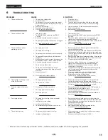
TROUBLESHOOTING
IMPACT 1040
6
TROUBLESHOOTING
PROBLEM
A. The unit will not run.
B. The unit will not prime.
C. The unit will not build or
maintain pressure.
D. Fluid leakage at the upper end
of the fluid section.
E. Excessive surge at the spray
gun.
F. Poor spray pattern.
G. The unit lacks power.
CAUSE
1. The unit is not plugged in.
2. Tripped breaker.
3. The pressure is set too low (pressure control
knob set at minimum setting does not supply
power to unit).
4. Faulty or loose wiring.
5. Excessive motor temperature.
6. ON/OFF switch is defective.
1. Inlet valve is stuck.
2. The PRIME/SPRAY valve is in the SPRAY
position.
3. Air leak in the siphon tube/suction set.
4. The pump filter and/or inlet screen is clogged.
5. The siphon tube/suction set is clogged.
1. The spray tip is worn.
2. The spray tip is too large.
3. The pressure control knob is not set properly.
4. The pump filter, gun filter, or inlet screen is
clogged.
5. Material flows from the return hose when the
PRIME/SPRAY valve is in the SPRAY position.
6. Air leak in the siphon tube/suction set.
7. There is external fluid leak.
8. There is an internal fluid section leak
(packings are worn and/or dirty, valve balls
are worn).
9. Worn valve seats
10. Motor powers but fails to rotate
1. The upper packing is worn.
2. The piston rod is worn.
1. Wrong type of airless spray hose.
2. The spray tip worn or too large.
3. Excessive pressure.
1. The spray tip is too large for the material
being used.
2. Incorrect pressure setting.
3. Insufficient fluid delivery.
4. The material being sprayed is too viscous.
1. The pressure adjustment is too low.
2. Improper voltage supply.
SOLUTION
1. Plug the unit in.
2. Reset the breaker.
3. Turn the pressure control knob clockwise to supply
power to the unit and increase the pressure setting.
4. Inspect or take to a Titan authorized service center.
5. Allow motor to cool.
6. Replace the ON/OFF switch.
1. Insert pusher stem.
2. Rotate the PRIME/SPRAY valve clockwise to the PRIME
position.
3. Check the siphon tube/suction set connection and
tighten or re-tape the connection with PTFE tape.
4. Remove the pump filter element and clean. Remove the
inlet screen and clean.
5. Remove the siphon tube/suction set and clean.
1. Replace the spray tip following the instructions that
came with the spray gun.
2. Replace the spray tip with a tip that has a smaller orifice
following the instructions that came with the spray gun.
3. Turn the pressure control knob clockwise to increase the
pressure setting.
4. Remove the pump filter element and clean. Remove the
gun filter and clean. Remove the inlet screen and clean.
5. Clean or replace the PRIME/SPRAY valve.
6. Check the siphon tube/suction set connection and
tighten or re-tape the connection with PTFE tape.
7. Check for external leaks at all connections. Tighten
connections, if necessary.
8* Clean the valves and service the fluid section following
the “Servicing the Fluid Section” procedure in the
Maintenance section.
9. Reverse or replace the valve seats following the
“Servicing the Fluid Section” procedure in the
Maintenance section of this manual.
10. Take unit to a Titan authorized service center.
1* Repack the pump following the “Servicing the Fluid
Section” procedure in the Maintenance section.
2* Replace the piston rod following the “Servicing the Fluid
Section” procedure in the Maintenance section.
1. Replace hose with a minimum of 50’ of 1/4” grounded
textile braid airless paint spray hose.
2. Replace the spray tip following the instructions that
came with the spray gun.
3. Rotate the pressure control knob counterclockwise to
decrease spray pressure.
1. Replace the spray tip with a new or smaller spray tip
following the instructions that came with the spray gun.
2. Rotate the pressure control knob to adjust the pressure
for a proper spray pattern.
3. Clean all screens and filters.
4. Add solvent to the material according to the
manufacturer’s recommendations.
1. Rotate the pressure control knob clockwise to increase
the pressure setting.
2. Reconnect the input voltage for 120V AC.
* Refer to the Service Manual (part number 2424937, available online) for complete instructions regarding this procedure.


