background image


TPM 053 

Version 1.0, May 30, 2017 

Page | 8 

MODULE INSTALLATION 

Gateway Installation and Operation Manual


Tp

m0530

02


Tp

m

053003


Tp

m

053004


Figure 2 

 Gateway Mounting 

Bracket


Figure 3 

 Gateway Module 

Figure 4 

 Interconnect Cable 

GATEWAY SYSTEM OVERVIEW 


The Titan Gateway is used to track your vehicle when in operation. The Gateway streams information on 
vehicle speed, stops, and position as well as receiving system information from the TD80 Level Gauge 
and Overfill Protection System. The Gateway uploads this information to a cloud-based server for data 
tracking and analysis. 


G

ATEWAY 

C

OMPONENTS


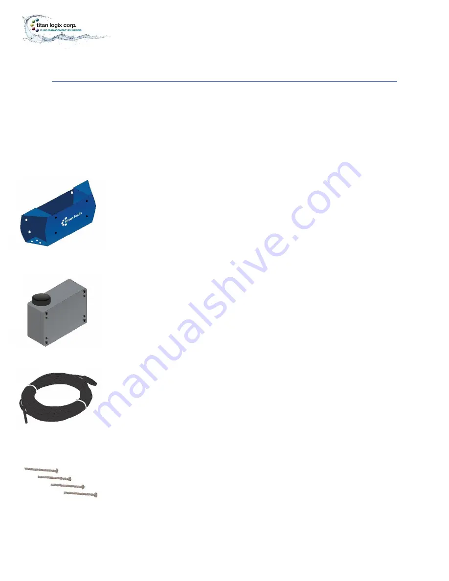
Gateway Mounting Bracket 

The mounting bracket acts as a secure seat for the Gateway module. It is mounted to a 
secure position on the vehicle and is to be installed as per the instructions provided in 
this manual. 


Gateway Module 

The Gateway module wirelessly transmits position and motion information of the 
vehicle, as well as gathering and transmitting data from the TD80 and Finch II 
components. The module sits securely inside the mounting bracket and connects 
directly to the TD80 and Finch II System via the Interconnect Cable. 


Interconnect Cable 

The interconnect cable is a wire cable that is supplied to connect the Gateway module to 
the Finch II display through a third party junction box.  


Module Mounting Bolts 

The module mounting bolts are supplied in order to secure the Gateway module to the 
mounting bracket.  


Tp

m

05

30

05


Figure 5 

 Module Mounting 

Bolts 

Содержание TPM 053

Страница 1: ...Tpm053001 Figure 1 Titan Gateway TITAN GATEWAY INSTALLATION OPERATION MANUAL TPM 053 Version 1 0 ...

Страница 2: ......

Страница 3: ... the Inside Sales number to speak with a representative and obtain an RMA number 2 Provide the serial number of the item with a description of issue and expected resolution 3 Describe the issue and indicate whether the item is defective missing components not suitable for the intended use or purchased in error 4 Indicate the expected resolution repair replacement return 5 Return the item together ...

Страница 4: ...ide the scope of this guide or specialized installations will require further documentation Please contact your nearest Titan Logix service facility with your requirements It is essential that this manual be read and understood for proper installation and operation of your new Gateway system WARRANTY Please see our Terms and Conditions for details about our product warranty There are no serviceabl...

Страница 5: ... manual will use the following standard safety terms and conventions to indicate conditions WARNING Indicates a hazardous situation which if not avoided could result in death or serious injury CAUTION Indicates a hazardous situation which if not avoided could result in moderate injury and or property damage NOTE Indicates an important message not related to personal injury or property damage Radio...

Страница 6: ...TY Titan recommends the following steps to protect the security of your system Change the Wi Fi password from the factory setting Keep all passwords documented and secure Password must use a combination of letters numbers and symbols and be at least 8 characters long with no spaces or the special characters ...

Страница 7: ... TD80 Components 9 Component Identification and Location 10 Features and Specifications 11 Features 11 Specifications 12 INSTALLING THE GATEWAY MODULE 13 Pre Installation 15 Mechanical Installation 16 Electrical Installation 18 Confirming Gateway Module Operation 19 GATEWAY OPERATION 20 GATEWAY UTILITY 21 Overview 21 Loading Utility Software 21 Gateway Utility Description 22 Gateway Status Screen ...

Страница 8: ...s and equipment 33 Optional tools and equipment as required 33 Gateway Troubleshooting 34 Gateway Communications Diagnostics 35 Gateway Communication Troubleshooting 37 Asset Management Dashboard Verification 3rd Party Provider 41 Repair 41 TD80 and Finch II 41 Gateway Module 41 System Wiring 41 Maintenance 41 REFERENCE DRAWINGS 42 Tank Truck Wiring Schematic 43 Trailer Wiring Schematic 45 Mountin...

Страница 9: ...onnect Cable 8 Figure 5 Module Mounting Bolts 8 Figure 6 TD80 Transmitter 9 Figure 7 TD80 Probe 9 Figure 8 Finch II Display 9 Figure 9 Component Location 10 Figure 10 Gateway Module Bottom View 11 Figure 11 Gateway Module Top View 11 Figure 12 Inserting the Gateway 17 Figure 13 Gateway Identification Label 21 Figure 14 Truck Wiring Schematic 43 Figure 15 Trailer Wiring Schematic 45 Figure 16 Mount...

Страница 10: ...g bracket acts as a secure seat for the Gateway module It is mounted to a secure position on the vehicle and is to be installed as per the instructions provided in this manual Gateway Module The Gateway module wirelessly transmits position and motion information of the vehicle as well as gathering and transmitting data from the TD80 and Finch II components The module sits securely inside the mount...

Страница 11: ... are available in two versions dual rod and coaxial probe for compatibility with a wide range of liquids Probe The probe guides the transmitted pulse and reflection from the surface of the liquid Probes are available in dual rod or coaxial versions and require a matching transmitter type The probe is mounted on the tank top and is connected to the bottom of the transmitter Dual rod probes are desi...

Страница 12: ...TPM 053 Version 1 0 May 30 2017 Page 10 MODULE INSTALLATION Gateway Installation and Operation Manual COMPONENT IDENTIFICATION AND LOCATION 1001138v1 0 Figure 9 Component Location ...

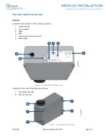
Страница 13: ...Gateway Module Bottom View Tpm053010 Figure 11 Gateway Module Top View FEATURES AND SPECIFICATIONS Features viewed from the bottom of the Gateway module 1 model number 2 serial number 3 IMEI 4 SSID 5 Interconnect Cable Connector 6 Status Light viewed from the top of the Gateway module 7 Mounting holes x4 8 External antenna ...

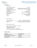
Страница 14: ...RS232 Cellular Radio Supports HSPA and GPRS EDGE Wi Fi 802 11b g n 2 4GHz Ethernet 10 100 Base T 2 Interconnect Cable Water and Dust Resistance IP66 when connected to Gateway Module Physical Dimensions 36 12 11m 0 3m length 0 235 6mm O D Material UV Resistant Black PVC 4 X 20AWG stranded 3 Gateway Configuration Utility Desktop or Laptop PC with Windows 7 or 10 Installed Display resolution 1024 X 7...

Страница 15: ...allation of the Gateway verify that the TD80 system is operating normally and that the Finch II firmware has been updated version 1 07 00 or greater Refer to the TD80 product manual TPM 001 and Finch II product manual TPM 010 For your convenience we have provided a checklist so that you can keep track of where you are in the installation process ...

Страница 16: ...on New Installation Mechanical Installation Checklist Checked Steps 1 Mounting Location Chosen 2 Mounting Bracket and Module Installed 3 Junction Box Installed 4 Air Pressure Switch Installed Trailer 5 Visual Inspection Performed Electrical Installation Checklist Checked Steps 1 Power Supply Verified 2 Gateway to Junction Box Connected 3 Finch Display to the Junction Box Connected 4 Air Pressure S...

Страница 17: ... 18 AWG 8 10 Stud Size Multi conductor trailer cable 2 conductors 16 14 AWG 4 or 5 conductors 16 14 AWG o 4 conductors for Gateway installation only o 5 conductors for Gateway and LoadMaxxtm installation Air pressure switch in a weatherproof enclosure for trailer installations Verify Facility Requirements Make sure that the installation area is in a weather protected area with adequate lighting he...

Страница 18: ...ch as fall restraint in accordance with facility regulations and policies Ensure fuses and components are appropriate for the area classification Follow all federal state provincial and local safety standards and industry recommended practices for the vehicle For example the Federal Motor Vehicle Safety Standards FMVSS and the American Trucking Association ATA Technology and Maintenance Council TM...

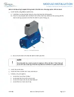
Страница 19: ...ith the antenna facing upwards and to the left when the unit is facing you c Secure the module to the bracket with the bolts provided NOTE Mounting bolts may only be inserted a maximum of four 4 times Thread lock will wear and cause loosening of the Gateway Module Call Titan for replacement bolts Install the Junction Box Install Air Pressure Switch for Trailer Installations Perform a Visual Inspec...

Страница 20: ...plices and interconnections should be made inside a weather proof enclosure or junction box to prevent premature failure due to corrosion Secure all wires and cabling with clips or cable ties Tighten all compression fittings Refer to the Tank Truck Trailer Wiring Schematics in the Reference Drawings section of this manual Verify the Power Supply Tank truck Switched accessory power Tractor trailer ...

Страница 21: ...wing steps 1 Turn on Gateway module by turning on the vehicle electrical accessory power or connecting to a fully charged battery power source 2 Confirm the Gateway module status light is showing a solid light then flashing at second intervals after initialization NOTE Once powered up the boot cycle for the module can take up to 2 minutes If the Gateway module is not operating as per the above con...

Страница 22: ...RATION Gateway Installation and Operation Manual GATEWAY OPERATION The Gateway System does not have any operational controls Operation is automatic when power is applied Indication of operation is by observation of the status light on the module ...

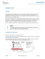
Страница 23: ...tware is updated in the field eliminating the need to return the Gateway to Titan for most changes The utility is compatible with desktop and laptop PCs with Windows 7 or 10 installed See the Configuration Utility Manual TPM 054 for detailed configuration and troubleshooting steps NOTE The Gateway Utility has the ability to save and retrieve configuration profiles in the event of a software update...

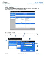
Страница 24: ...er will see once the Utility is launched This screen displays the general condition and connection status of the Gateway module Connecting to the Network Once the Utility has launched click on Network Connect then choose the correct network from the dropdown If the correct network does not appear in the list click on the refresh button Enter your supplied password and click Connect ...

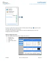
Страница 25: ...ger typically found at the bottom right hand corner of the screen For details on connecting to the network and for connection troubleshooting steps refer to the Configuration Utility manual TPM 054 Gateway Configuration Screen This screen displays the Gateway settings It displays information on Remote server Network servers DNS servers Finch II communication GPS ...

Страница 26: ...tings from the Gateway 1 Connect to the Gateway through Wi Fi 2 Click Configuration Gateway Retreive From Gateway 3 Record the settings in a text file or capture a screenshot with the configuration settings save in a secure place and use for reference when needed 4 Optionally click Save To File select a folder and filename to save the configuration Use these settings to compare with the configurat...

Страница 27: ...label on the module for the correct number The factory set WI FI password is tlcgateway Changes to the password can be made using the configuration utility See the Configuration Utility Manual TPM 054 for further details In the event the Wi Fi password is lost or forgotten or if the password needs to be reset to the factory setting contact Titan NOTE Keep the passwords in a secure place and use fo...

Страница 28: ... your new unique password Enter the new password again Click to change password 1 Once the password has been reset restart the Gateway device or cycle the power 2 Click on RESTART GATEWAY DEVICE 3 Choose Yes No or cycle the power After restarting the Gateway device the user must perform the network connection steps listed previously ...

Страница 29: ...TPM 053 Version 1 0 May 30 2017 Page 27 SOFTWARE Gateway Installation and Operation Manual ...

Страница 30: ...blinking second ON and second OFF 2 Launch the Gateway Configuration Utility Standard a Establish a Wi Fi connection with the Gateway b Save the configuration settings using the Gateway Configuration Management procedure in this manual c Click the Gateway Status selection 3 Optional Customized Configuration a Go to the Gateway Configurations page b Click Open From File c Browse to the configuratio...

Страница 31: ...ion and Operation Manual UPDATES Whenever there is an internet connection the Utility will search for and auto update the program The program will prompt if you want to do the update Once the program is launched you will see the following status as the utility updates ...

Страница 32: ...Titan recommends the following steps to protect the security of your system Change the Wi Fi password from the factory setting Keep all passwords documented and secure Password must be at least 8 characters Use a combination of letters numbers and symbols Do not use spaces or these special characters ...

Страница 33: ...TPM 053 Version 1 0 May 30 2017 Page 31 TROUBLESHOOTING MAINTENANCE Gateway Installation and Operation Manual COMMISSIONING TO BE DETERMINED ...

Страница 34: ... of the system Failure of any checklist step below indicates a problem to be resolved This check is easily performed remotely through a Wi Fi connection Note that the vehicle must provide adequate power for a successful health check Error free steps 2 through 6 imply that the Status light is indicating normally Step Detail 1 Observe the Gateway Status light Confirm Blinking second ON second OFF 2 ...

Страница 35: ...TD80 system and Gateway components will lead to successful troubleshooting and repair For TD80 system issues refer to the Finch II product manual TPM 010 for troubleshooting and repair details The following test and troubleshooting guidance is for Gateway issue resolution Required tools and equipment Laptop computer with Standard Gateway Configuration Utility installed Digital Multimeter DMM Elect...

Страница 36: ...Status light is off Power is not turned ON electrical failure or internal Gateway failure 1 Confirm adequate power supply and adequate operating voltage at the power and ground terminals to the following components Finch II display Gateway 2 Verify all cables are connected and wires are secure on the connections below Gateway interconnect cable to the junction box Power supply wiring Internal junc...

Страница 37: ... Installation and Operation Manual Gateway Communications Diagnostics Perform each of the diagnostic steps below before performing any communications troubleshooting to determine the status of the Gateway system Issue resolution may require contacting your Titan representative ...

Страница 38: ... communication Gateway Status screen Confirm the following a Communication Established checked b Received Packet Counts incrementing at the expected rate see the Sensor Data Rate setting 5 Cellular connection Gateway Status screen Confirm the following a PPP Link Status checked b IMEI c SIM Card Detected checked d Signal Strength good 6 Remote server connection Gateway Status screen Confirm the fo...

Страница 39: ...ough Wi Fi to the Configuration Utility Make sure the correct Wi Fi network has been selected and the corresponding password has been entered correctly Retry the Wi Fi network connection Condition Resolution No SSID Available for the Gateway 1 Ensure there is power to the system 2 Ensure the Gateway is within transmission range 3 Ensure the SSID is correct 4 Ensure the Wi Fi adapter is turned on ...

Страница 40: ...nstallation and Operation Manual Condition Resolution Sim card is not detected Contact Titan Condition Resolution PPP link is not detected 1 Check the cellular signal strength 2 Check the APN Server settings 3 Cycle the power to the Gateway 4 Observe the PPP link after 2 minutes ...

Страница 41: ...I display unit are secure 2 Confirm that the Finch II and TD80 are operating normally as per TPM 010 3 Confirm the Finch II firmware version supports Gateway operation firmware version 1 07 00 or greater Condition Resolution Remote network server is not communicating 1 Check the Remote Server and DNS settings 2 Check PPP link status is checked 3 Cycle the power to the Gateway 4 Observe the PPP lin...

Страница 42: ...y Installation and Operation Manual Condition Resolution Gateway date and time are incorrect Check the Network Servers SNTP Server setting Condition Resolution Gateway is not sending data at the expected rate Check the GPS and Sensor Rate settings in the Gateway Configuration ...

Страница 43: ...PM 001 and Finch II product manual TPM 010 Gateway Module The Gateway module is not field repairable There are no user serviceable components inside Return the unit to Titan for repair or replacement System Wiring It is not recommended to repair damaged TD80 system or Gateway cabling Replace the cable to maintain the weather proof quality of the interconnect wiring Temporary or emergency field rep...

Страница 44: ...TPM 053 Version 1 0 May 30 2017 Page 42 DRAWINGS Gateway Installation and Operation Manual REFERENCE DRAWINGS ...

Страница 45: ...DRAWINGS Gateway Installation and Operation Manual TANK TRUCK WIRING SCHEMATIC 1001136v1 0 Gateway Interconnect Cable Connection Details RD Power BLK Ground GRN RS232 from the Gateway WHT RS232 to the Gateway Figure 14 Truck Wiring Schematic ...

Страница 46: ...wires 5 6 7 8 and 9 3 Connect Power and Ground to Junction Box wires 10 and 11 Wiring Connection Gateway Interconnect Cable Wires Junction Box Terminals Air Pressure Switch Terminals Vehicle Power from Switched Accessory Power Finch II Terminals 1 RD BLU 2 BLK WHT 3 WHT YLW 4 GRN GRN 5 WHT GND IN 6 BLK PWR IN 7 Optional reserved for LoadMaxxtm BRN RX2 8 GRN RX1 9 YLW TX1 10 WHT Chassis Ground 11 B...

Страница 47: ... DRAWINGS Gateway Installation and Operation Manual TRAILER WIRING SCHEMATIC 1001137v1 0 Gateway Interconnect Cable Connection Details RD Power BLK Ground GRN RS232 from the Gateway WHT RS232 to the Gateway Figure 15 Trailer Wiring Schematic ...

Страница 48: ...itch to Junction Box wires 10 and 11 4 Connect Power and Ground to Junction Box wires 12 and 13 Wiring Connection Gateway Interconnect Cable Wires Junction Box Terminals Air Pressure Switch Terminals Vehicle Power from J560 Nose Box Socket Finch II Terminals 1 RD BLU 2 BLK WHT 3 WHT YLW 4 GRN GRN 5 WHT GND IN 6 BLK PWR IN 7 Optional reserved for LoadMaxxtm BRN RX2 8 GRN RX1 9 YLW TX1 10 BLU COM 11...

Страница 49: ...allation and Operation Manual 1001135v1 0 Figure 16 Mounting Template MOUNTING TEMPLATE DRILLING GUIDE NOTE Drawing 1001135v1 0 is not to scale and is provided solely for the purpose of showing the bolthole pattern required in the mounting of the Gateway bracket ...

Страница 50: ...4130 93 Street Edmonton Alberta Canada T6E 5P5 P 780 462 4085 F 780 450 8369 Toll Free 1 877 462 4085 TSX V TLA Sales Department Email us at sales titanlogix com Service Department Email us at service titanlogix com Find us online at www titanlogix com ...

Отзывы: