Tiso Optimus RB392 Series Скачать руководство пользователя страница 18


18 


3.3. Protective induction loops 

 
The Boom Barrier control unit may include additional option 


protective induction loops

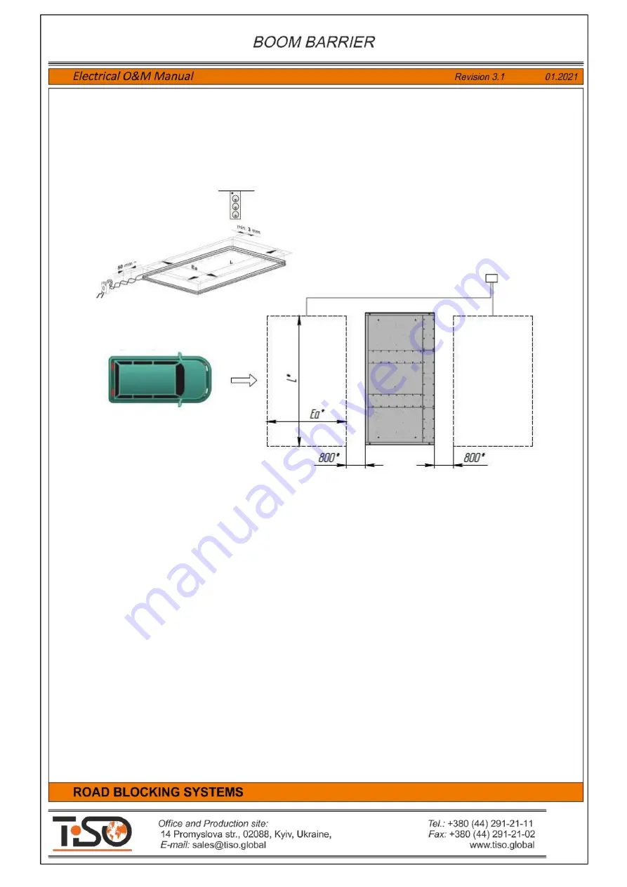
One  or  two  induction  loops  are  installed  in  roadbed  next  to  the  Boom  Barriers,  are  connected  to 

control unit and are used to prevent the Boom Barrier raising when a vehicle is on induction loop. 


Fig.10 - 

Example of induction loop layout next to the road blocker 


If Boom Barrier has 

induction loop 

option, then control unit contains one or two controllers of induction 

loops 

B3-A4.  Safety  Loop  Detector  A  EMX  ULTRADIN  * 

and 

B3-A4.  Safety  Loop  Detector  A  EMX 

ULTRADIN *

The scope may also include some cables 

SIF1.0 

for preparation of induction loops.  

The maximum allowable distance from induction loop to control unit is 

20 m

Induction  loop  responds  to  vehicle  metal  and  at  its  location  there  should  not  be  metal  in  road 

surface. Minimum distance from induction loop to metal parts is 

500  mm

A  trench  of 

50-70  mm 

depth  and 

15-25  mm 

width  according  to  induction  loop  size  is  made  for 

installation  of  induction  loop  in  road  surface.  A   trench  is  also  made  from  the  edge  of  induction  loop  to 
control unit. 

Induction  loop  is 

3-4 

turns  of  cable 

SIF1.0 

to  be  installed  in  trench  the  ends  of  which  are  twisted 

between  them  and  connected  to  induction  loop  controller  of  control  unit.  Cable 

SIF1.0 

can  be  laid  in 

plastic corrugated tube or plastic pipe. After induction loop is laid in pipe it is filled with sand and covered with 
cement or asphalt grout. 

Содержание Optimus RB392 Series

Страница 1: ......

Страница 2: ...eration 13 2 2 Troubleshooting 15 3 1 Wire remote control panel RB111 16 3 2 Boom Barrier wireless control 17 3 3 Protective induction loops 18 4 Road Blocker operator s guide 21 5 Boom Barrier electr...

Страница 3: ...control unit is a controller with additional electric parts and is designed to control the Boom Barrier The control unit is assembled in a plastic box and is located inside the Boom Barrier rack Powe...

Страница 4: ...4 1 2 Description of the versatile controller PCB349 Fig 2 Illustration of controller PCB349 with identification of its components inputs and outputs...

Страница 5: ...inal block for connection of the Road Blocker 1 control inputs sensors and additional devices 9 Terminal block X6 OUT1 Outputs 1 Terminal block for connection of the Road Blocker 1 actuating devices a...

Страница 6: ...onnection of neutral N of the Road Blocker1 motor 10 MOTOR 1 PE Output for connection of protective earthing PE of the Road Blocker1 motor When the road blockers are used with peripheral hydraulic uni...

Страница 7: ...of DOWN position sensor The Road Blocker will stop when it is activated during lowering When the input is active then it will not respond to lowering command 23 INP SENSOR 3 1 Input for connection of...

Страница 8: ...d during lowering When the input is active then it will not respond to lowering command 53 INP SENSOR 3 2 Input for connection of pressure valve It is used only in the road blockers with accumulator 5...

Страница 9: ...th accumulator 36 INDICATION LED 1 Output for connection of the Road Blocker 1 additional LED 1 display module anode 37 INDICATION LED 1 Output for connection of the Road Blocker1 additional LED 1 dis...

Страница 10: ...r voltage of remote control panel DI 601 39 RS485 A1 Signal RS485 A of angular position sensors DI 601 40 RS485 B1 Signal RS485 B of angular position sensors DI 601 41 GND Common wire GND of angular p...

Страница 11: ...sensors induction loops or safety photocells 25 26 55 56 INP Safety When the switch is OFF then road blocker will be stopped when signal is coming on INP Safety When the switch is ON then road blocker...

Страница 12: ...econds selected by the TIME1 after each raise or lower command and will stop after this timeout has been completed The timeout of raising and lowering increases when the regulators is rotate clockwise...

Страница 13: ...lights external siren are connected to control unit General connection diagram of the Boom Barrier and additional devices is shown in Annex 1 Wiring diagram of the Boom Barrier with control unit and a...

Страница 14: ...lowering are determined by the of the position sensors position limit switches and magnets If appropriate end position sensors to be adjusted according to the diagram shown in Fig 5 Fig 5 Adjustment...

Страница 15: ...well as errors to be eliminated and connection to be made properly 2 Continuous operation of motor after reaching UP and DOWN position by Boom Barrier End position sensors Sensor TOP or Sensor BOT ar...

Страница 16: ...ar DOWN button will be blinking during lowering When Road blocker reaches the lowermost position and stops then the lamp near DOWN button will be steadily lit DOWN position display Road blocker is sto...

Страница 17: ...pendant Satel T 2 to be pushed to raise the road blocker Red DOWN button of remote control pendant Satel T 2 to be pushed to sink the road blocker To add new remote control pendants Satel T 2 in stor...

Страница 18: ...for preparation of induction loops The maximum allowable distance from induction loop to control unit is 20 m Induction loop responds to vehicle metal and at its location there should not be metal in...

Страница 19: ...20 6 10m 3 3 2 0 975m 4 1 22m 22 6 71m 3 3 2 0 975m 4 1 22m 24 7 32m 3 3 2 0 975m 4 1 22m 26 7 93m 3 3 2 0 975m 4 1 22m 28 8 54m 3 3 2 0 975m 4 1 22m 30 9 14m 2 3 2 0 975m 4 1 22m 32 9 75m 2 3 2 0 97...

Страница 20: ...s of cable SIF1 0 of each induction loop to be connected to terminals LOOP and LOOP of Safety Loop Detector EMX ULTRADIN induction loop controller of control unit Fig 11 Diagram of connection of induc...

Страница 21: ...dependent road blockers connected to one control unit The Road Blocker wireless control pendant Satel RE 2K is equipped only with buttons UP and DOWN but is not equipped with button STOP The operator...

Страница 22: ...rgency stop button Emergency Stop When this button is pushed then the Boom Barrier will be stopped and will be standstill until it is released and new commands UP or DOWN are generated When the button...

Страница 23: ...damages of the Boom Barrier to be visually inspected Integrity of circuit of protective earthing P of Boom Barrier metal parts with circuit of earthing P of power supply network earthing circuit resis...

Страница 24: ...X5081 03PFS 5 08 mm 3 pin 1 12 NX5081 TF Pin for 5 08mm Connector 6 13 Connector WAGO 264 336 1 14 Connector WAGO 264 354 1 15 Connector WAGO 264 357 1 16 Connector WAGO 264 361 1 17 Thermostat KSD970...

Страница 25: ...25 Annex 1 Boom Barrier Connection Diagram...

Страница 26: ...26 Annex 2 Wiring Diagram of Boom Barrier with additional devices...

Отзывы: