14
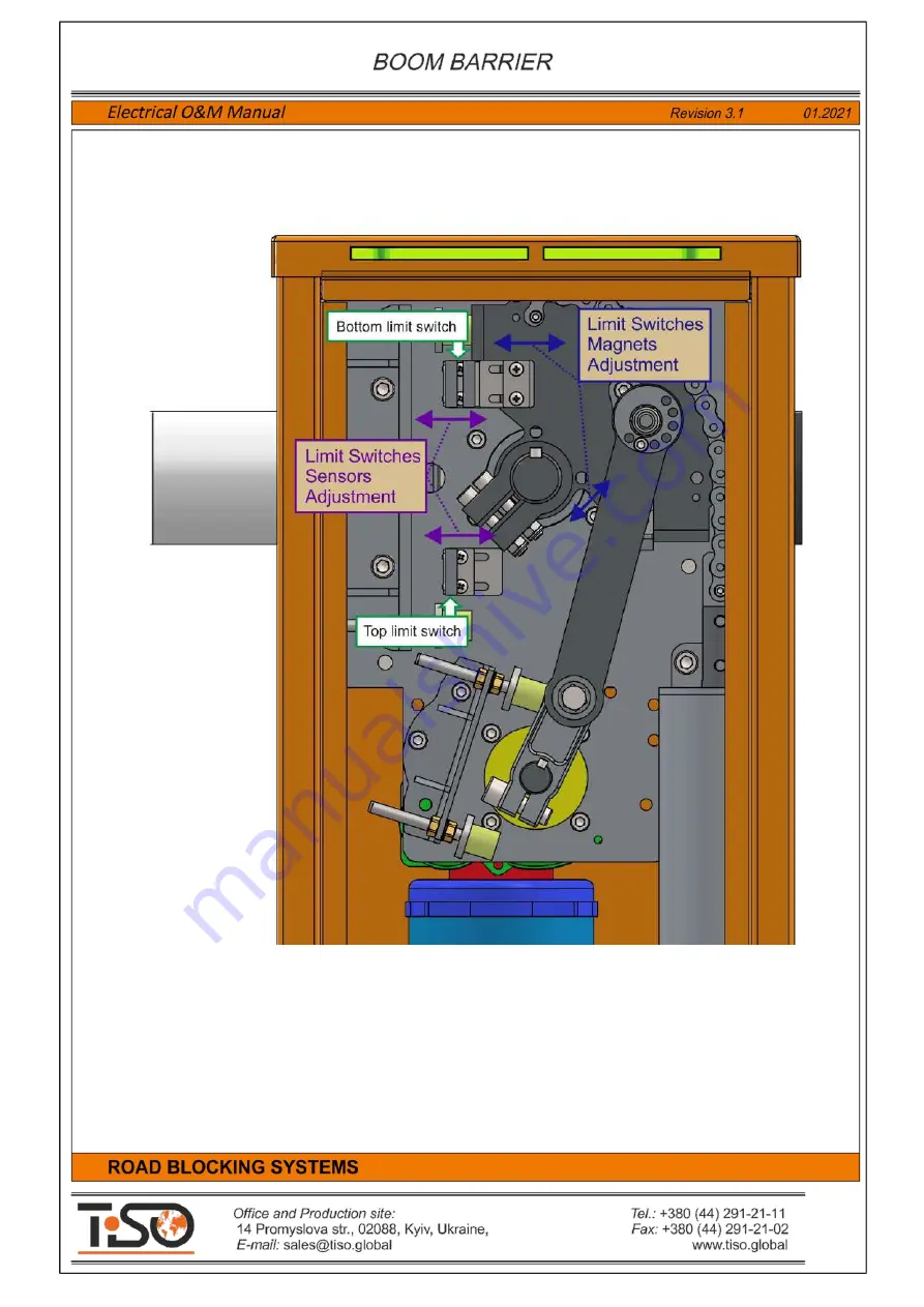
The Boom Barrier stop or deceleration points during raising or lowering are determined by the of the
position sensors position
–
limit switches and magnets.
If appropriate, end position sensors to be adjusted according to the diagram shown in Fig. 5.
Fig.5
- Adjustment of the Boom Barrier position sensors - limits switches and magnets.
Содержание Optimus RB392 Series
Страница 1: ......
Страница 25: ...25 Annex 1 Boom Barrier Connection Diagram...
Страница 26: ...26 Annex 2 Wiring Diagram of Boom Barrier with additional devices...


