

1
2
Quick Start Guide
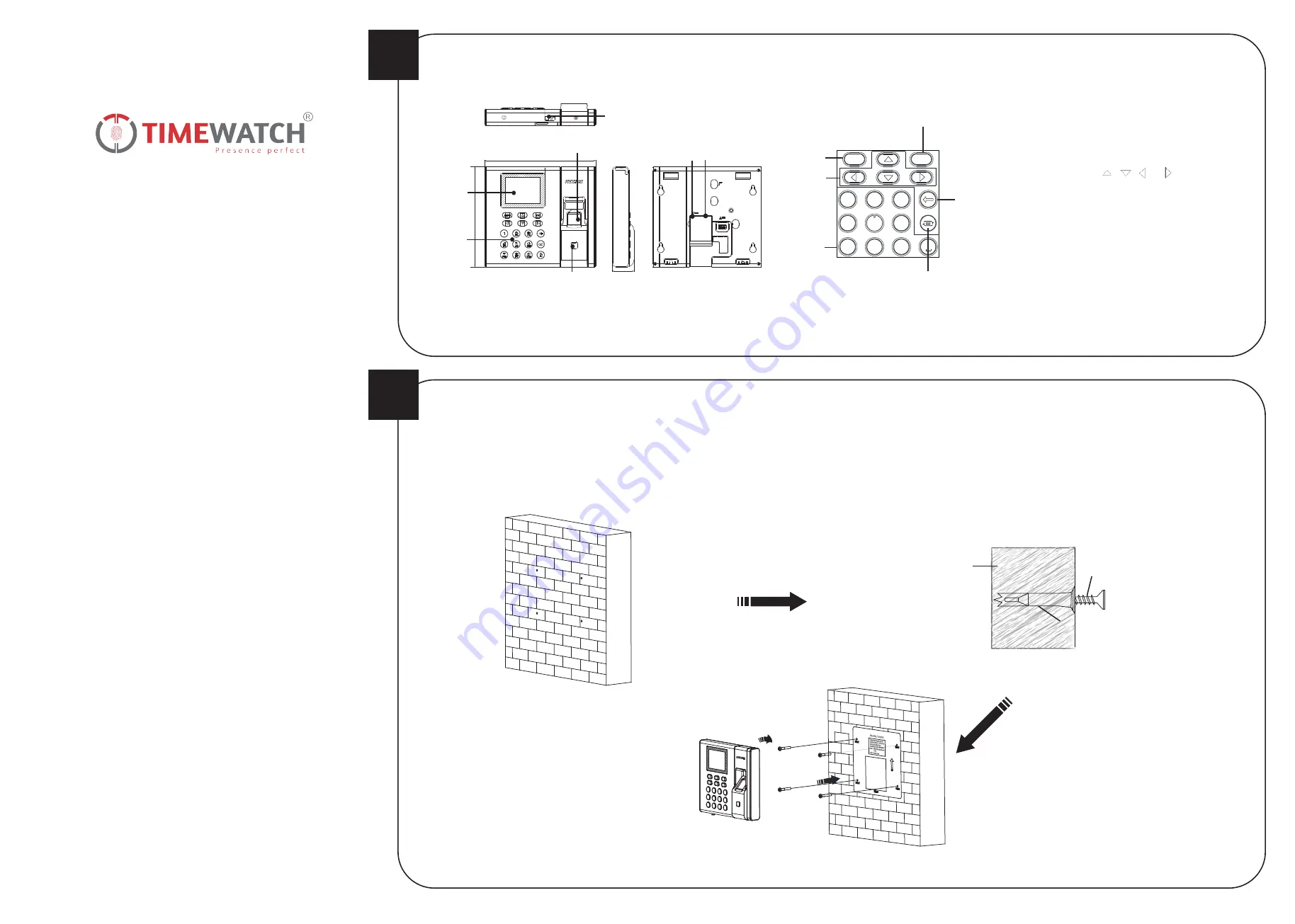
Appearance
Installation
OK Key:
Press the key and confirm operations. Hold the key
for 3 s to enter the login interface.
Deleting Key:
Press the key to delete the entered letter or
number
.
If the device supports connecting lithium battery, long press
the key to power off the device.
Numeric Keys/Letter Keys:
Press the key to enter numbers
or letters.
Key 0 can also represent a space key except you are using the
number input method.
Exiting Key:
Press the key to exit the menu.
Direction Keys:
Press , , and
to move the cursor
on the screen.
Editing Key:
Press the key to enter the editing status.
You can shift among numbers/lowercases, numbers/uppercases
and symbols.
Keypad Descriptions
ESC
OK
1
2
ABC
3
D
EF
4
G
H
I
6
MNO
7
PQRS
8
TUV
9
WXYZ
5
JKL
Exiting Key
Direction
Keys
Numeric Keys/
Letter Keys
OK Key
Editing Key
Deleting
Key
Notes:
1. The pictures here are for reference only. Some models do not support
card swiping function. For details, refer to the actual products.
2. If you enable the attendance status function, the OK key, the direction
key, and the exiting key can be the shortcut key of the attendance status.
Display Screen
Keypad
Fingerprint Recognition Area
Card Swiping Area
USB Interface
Network
Interface
14
0 mm
3
0 mm
15
5 mm
Power
Interface
4. If there is a cable hole on the wall, route the cables from the
wall and connect them with the interfaces on the device rear
panel.
If there is no cable hole on the wall, connect the cables with the
interfaces on the device rear panel and make sure the cables
will come out from the device bottom.
5. Align four holes of the device rear panel with the fixed screws
and hang the device on the wall.
M4 Expansion Bolt
The additional force shall be equal to three times the weight of the equipment but not less than 50 N.
The equipment and its associated mounting means shall remain secure during the test. After the test, the equipment, including any associated mounting plate, shall not be damaged.
2. Insert 4 supplied expansion sleeves of the setscrews (4_KA4×22-SUS) in
the drilled holes respectively.
3. Fix and fasten the expansion bolts in the expansion sleeves respectively.
Note:
Reserve 5.2 mm to 5.5 mm of expansion bolts outside the wall
for hanging the device.
Wall
Steps:
1. Stick a mounting template on the wall at a required height, and drill 4
holes according to the mounting template on the wall.
Expansion Sleeve
0
ULtraFP8503 & T20
Series
Fingerprint Time Attendance Terminal


