15
The sweep magnifier of the display oscilloscope provides an
analog expansion of the trace. The magnify function on the DSA
(via the SEARCH key) provides a digital expansion. 102 words of
the digitising memory are used to fill the 1024 words of the trace
by using linear interpolation to generate nine extra words
between each pair.
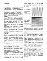
When a waveform has been captured at a very low number of
samples per cycle, MAG can be used to observe it. If the
waveform is sinusoidal in nature, linear interpolation will not re-
produce the waveform shape very well if the number of samples
per cycle is less than ten. The DSA524 provides the alternative of
sine interpolation which provides a good reconstruction of a
sinewave from only four samples per cycle by using a mathe-
matical curve fitting algorithm.
3.
Reduce the timebase speed to 100us/div, this reduces the
number of samples per cycle to five. Press SEARCH three
times to select MAG mode, note that the displayed wave-
form shape is poor. Press the SINE INTERP key, the lamp
will illuminate, note that the displayed waveform shape is
greatly improved.
Trace Multiply
(Start with the DSA reset and the generator set to SINE, 20kHz,
5V pk-pk.)
The trace multiply function (A = AxB) allows the product of two
waveforms to be displayed. Thus, for example, if Trace A was
displaying a voltage waveform and Trace B was displaying a
corresponding current waveform, trace multiply could be used to
display the power waveform on Trace A.
1.
Note the waveforms obtained on each trace then press
SHIFT followed by A = AxB (key 2), RUN/HOLD will be set
to HOLD, note that the multiplied waveform appears on
Trace A.
2.
Note that trace multiply cannot be used while digitising is
taking place (pressing RUN or SINGLE will cancel the
function). Note also that ADD B and GAIN VARIABLE on
Trace A are disabled after trace multiply has been
selected. Press ESCAPE to return Trace A to its normal
display.
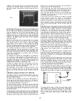
The multiplied waveform is scaled using units of one screen
division with the centre of the screen being zero. The traces are
multiplied exactly as they appeared on the oscilloscope display
including offsets introduced by the trace position controls. Thus
at a point where the position of Trace A is +2 divs and of Trace B
is -1.5 divs, the value of the multiplied waveform will be -3 divs.
It should be noted that if either trace has values greater than ±1
divs then overflows could occur on the multiplied waveform. The
displayed waveform is limited to ±4.25 divisions and
consequently -3 divs multiplied by -2.5 divs will be displayed as
+4.25 divs instead of +7.5 divs.
4.
Use the Trace A and Trace B variable controls to alter
the amplitude and position of the waveforms prior to
multiplication. Note the results. Press ESCAPE to exit.
Program Mode
(Start with the DSA reset and the generator set to SINE, 20kHz,
5V pk-pk.)
The DSA524 can operate as a fully programmable instrument. It
can "learn" individual or sequential front panel settings, store
them in non-volatile memory, and "replay" them on demand. Up
to 50 settings can be stored.
Each front panel setting includes the state of every key and
rotary control and the source of each trace waveform. Thus if a
setting is "learned" which includes a trace recalled from a wave-
form store, that same store will be recalled again when the
setting is "re-played". Thus reference waveforms can be recalled
automatically within PROGRAM mode.
1
Select "learn" mode by pressing LEARN (the LEARN lamp
will illuminate). Note that the screen shows the message
"NEXT POSITION = 01".
2.
Press SET(NN), followed by key 3, followed by key 0 (for
'example). The screen will show the message "STORED
IN MEM = 30" followed by "NEXT POSITION = 31",
showing that the current front panel settings have been
stored in memory position 30.
3.
Now reset the front panel including time/div, volts/div,
input coupling, rotary controls etc. Press SET/NEXT, the
screen will show "STORED IN MEM = 31" followed by
"NEXT POSITION = 32". Now recall waveform memory
01 onto Trace B and then press SET/NEXT again.
Further sets of front panel settings have now been
stored in positions 31 and 32.
4.
Exit "learn" mode by pressing the LEARN and REPLAY
keys simultaneously, and select "replay" mode by
pressing REPLAY (the R PLY lamp will illuminate). The
screen will show "NEXT POSITION = 33", showing that
the most recently used position was 32.
5.
Press SET(NN) 30, the front panel will reset and the
screen will show "REPLAYED MEM = 30" followed by
"NEXT POSITION = 31". Press SET/NEXT, the front
panel will be reset again. Press SET/NEXT again, the
front panel will be reset and the waveform in memory 01
will appear on Trace B.
6.
Press SET(NN) 30 to reset the front panel to its original
settings and exit "replay" mode by pressing the LEARN
and REPLAY keys simultaneously.
Hardcopy Output
The DSA524 can provide hardcopy output via dot matrix printer
(Epson codes compatible, with a serial interface), a digital X-Y
plotter (HP-GL codes compatible, with a serial interface), an
analog X-Y plotter, or an analog Y-T chart recorder.
Because different users will wish to use different types of
printers or plotters, this subject cannot be usefully covered in
this tutorial. Please refer to the reference section of the manual
for a description of the PRINT and PLOT functions.
Remote Interfacing
The RS-423 serial interface (RS-232 compatible) and the
optional IEEE-488 interface of the DSA524 enable it to be
connected to a wide variety of other equipment. The interfaces
can be used for full remote control of the DSA (anything that
can be controlled from the keyboard can also be controlled via
the interfaces), and for bi-directional transfer of waveform data.
Refer to the reference section and appendices for full details.
A Final Word
This tutorial has covered most of the functions of the DSA524 in
terms of its use with a display oscilloscope. The DSA524 is a
highly sophisticated and versatile instrument which has many
further uses which have not been touched upon in the tutorial,
in particular its use as an interfaceable and programmable
instrument. Some of its other facilities are covered in the
reference section of the manual, the appendices, or in individual
application notes.


