11
2.
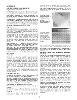
When RUN /HOLD is set to HOLD, digitising is stopped.
Press RUN /HOLD to set it to HOLD, then change the out-
put of the generator, and note how the display remains
unchanged.
3.
When RUN /HOLD is set to HOLD, pressing the SINGLE
key causes digitising to occur once. Press SINGLE and
note how the display is updated to the new amplitude/fre-
quency of the generator.
Controlling the Input Channels
(Start with the DSA reset and the generator set to SINE, 20kHz,
5V pk-pk.)
The two input channels CH1 and CH2 are identical. They control
the levels of the input signals before they are digitised.
1. The input coupling switches (AC/DC and GND) perform
the same function as on a normal oscilloscope. Try
changing them. Note that when CH1 is grounded the
position of the CH2 waveform on the display becomes
random, this is because the trigger signal has been
removed. Set both channels back to AC.
2.
The input sensitivity is variable between 10V/div and 2mV
/div. The key with a downwards arrow sets a lower
volts/div setting and the key with the upwards arrow a
higher one, the keys autorepeat if held depressed. Try
changing the CH1 sensitivity upwards and downwards.
Note that when the input exceeds approximately ± 4.25
divisions on the screen it becomes "clipped", this is
because the range of the digitiser is limited to ± 4.25
divisions. When the input signal is outside the range of the
digitiser, the AUTO/OVLD lamp flashes, this is to warn the
user that the signal is not being correctly digitised (no
damage is being done).
3.
Autoranging input sensitivity can be selected on either
channel. Press both arrow keys simultaneously, the AUTO
lamp will come on. Try changing the amplitude of the gen-
erator output and note how the sensitivity is automatically
changed to maintain a screen amplitude of between about
1.5 and 3.5 divisions. To cancel autoranging press either
arrow key once.
4.
If the DC level of the input signal is not zero, it may be
necessary to apply a DC offset to the signal before it is
digitised. This can be done with the rotary controls
marked OFFSET which can add up to ±8 divisions of
offset. Press the key marked ZERO(VAR) to enable
variable offset (it is enabled when the lamp is off). Try
rotating the offset control and note how the DC level of
the signal is changed. Press the key again to return to
zero offset.
5.
The digitising for each channel can be controlled
individually by the keys marked "ON/OFF". These allow
one channel to be "held" while digitising continues on the
other channel. Try turning CH1 off and changing the fre-
quency of the generator, note that the CH2 display con-
tinues to be updated but that the CH1 display is frozen.
Note that if both channels are turned off, RUN/HOLD will
be automatically set to HOLD.
Controlling the Traces
(Start with the DSA reset and the generator set to SINE, 20kHz,
5V pk-pk.)
The DSA524 can display two traces simultaneously, the traces are
called Trace A and Trace B. Whereas the input channel controls
(CH1 and CH2) operate on the input to the digitiser, the trace
controls operate on the output signals which are sent to the
display oscilloscope. Normally Trace A is used to display CH1, and
Trace B is used to display CH2, but the traces may alternatively
be used to display waveforms stored in the indexed memories.
1.
The POSITION controls define the position of the traces
on the screen and provide ± 4.25 divisions of adjustment.
Press the key marked HOME(VAR) to enable variable posi-
tion (it is enabled when the lamp is off). Try varying the
position of the traces, note that whereas OFFSET only
affects the waveform when digitising is taking place, PO-
SITION affects it at all times whether RUN/HOLD is at
RUN or HOLD. Press the key again to "home" the trace
position.
2.
The GAIN VARIABLE controls can reduce the amplitude
of each trace by any factor between one (fully clockwise)
and five (fully anti-clockwise). Press the CAL(UNCAL) key
to enable variable gain (it is enabled when the lamp is
off). Try varying the gain and note that, because it is
within the trace control section, it operates on the
waveform after it has been digitised and continues to
operate even when the waveform is "held". Press the
key again to return to calibrated gain.
3.
Each trace is turned off by simultaneously pressing the
keys marked CH1 (or CH2) and RCL(NN). Try turning a
trace off (note that the CH key should be pressed first to
avoid setting RUN/HOLD to HOLD). To turn the trace
back on press the CH1 (or CH2) key. Do not try using
the RCL(NN) or SAVE(NN) keys at this stage.
4.
Trace B has a key marked INV (Invert). Press this key
and note that the trace becomes inverted. Press it again
to turn inversion off.
5.
Trace A has a key marked ADD B. Press this key and
note that Trace A then displays the sum of the Trace A
waveform and the Trace B waveform. Note that this can
also be used for subtraction when Trace B is set to
invert. Note also that because add and invert are trace
controls they can still be used when either or both
channels are "held".
Setting the Timebase
(Start with the DSA reset and the generator set to SINE, 20kHz,
5V pk-pk.)
The timebase is adjustable between 50ns/div and 200mins/div.
The timebase speed is set using the two TIME/DIV keys which
autorepeat if held depressed. Setting the timebase speed also
sets the DSA into one of three modes of operation:
1.
Normal Mode
1a.
Turn off CH2 and Trace B. Try changing the generator
frequency up and down and changing the timebase
speed to maintain a roughly constant period on the
screen (within the range 5us/div to 100ms/div). This is
the "normal" mode of operation whereby the display is
updated each time 40.96 divisions of the waveform have
been digitised. Note that at low timebase speeds the
display update rate becomes slower, this is because of
the increased digitising time (at 100ms/div digitising
takes 4.096 seconds).
1b.
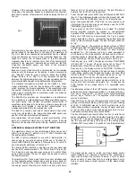
Now set a generator frequency of 100Hz and a timebase
speed of 5ms/div. Increase the generator frequency to
1kHz, note that the waveform is starting to become diffi-
cult to view. Increase to 2kHz, note that the waveform
can no longer be interpreted as a sine waveform and
appears to have random patterns superimposed onto it.
This is visual aliasing (caused by the vertical separation
between sample points being much greater than the
horizontal separation). Turn on the sweep magnifier of
the display oscilloscope to observe that the waveform is
roughly sinusoidal but is made up of only 10 samples per
cycle.
1c.
Now increase the generator frequency to 20kHz and vary
it slightly, note that the waveform changes erratically as
the generator frequency is changed, and that waveforms
with an apparent frequency down to a few Hz can be
obtained. This is true aliasing, caused by the sampling
frequency being less than twice the signal frequency
(the sampling rate equals 100 divided by the time/div,
so at 5ms/div the sampling rate is 20kS /s).


