background image

PTR306 / PTR306B Recoaters with Linear Proof Testers


Chapter 6: Controlling the PTR306/PTR306B


Rev D, October 2, 2020 

Page 19


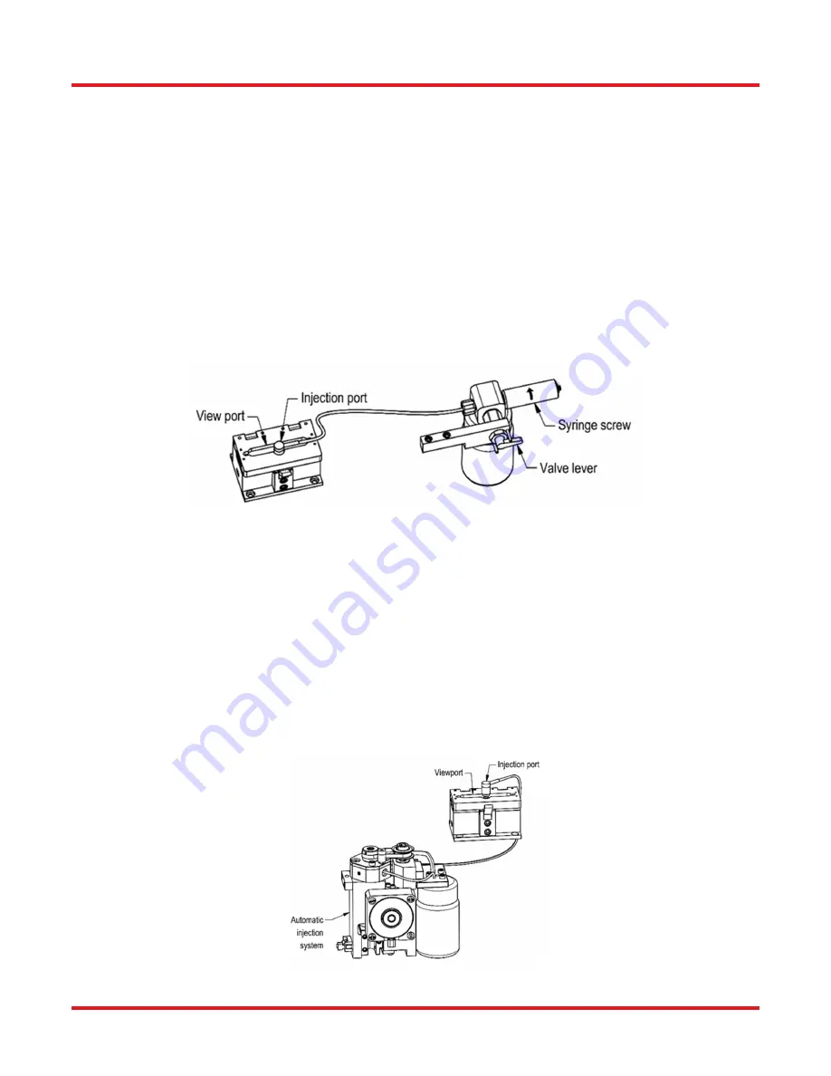
Recoating (PTR306B) 

Make sure that the selection lever is in the inject position (lever up). Once the fiber has been captured in the recoat 
mold assembly, the injection syringe should be screwed in (turned clockwise) to inject the UV acrylate material into 
the mold cavity. The material will flow from the injection port, down a shallow channel, into the recoat cavity. The 
syringe should be turned slowly to give the material time to flow smoothly along the injection path. 

Use the viewport in the recoat top to watch the material flow into the mold. Continue turning the injection syringe 
until the acrylate material reaches both coating interfaces of the exposed section of fiber. A slight migration of the 
acrylate material outside of the injection path between the two mold plates can be expected. The bottom mold plate 
has an optical coating that prevents this material from curing and forming a characteristic mold flashing. Excessive 
flashing flow indicates that the plates did not mate flush together. This is generally caused by dirt particles on the 
mold plates and/or by trying to recoat a fiber that has a larger coating diameter than the recoat mold. 

Note: If the syringe end of travel is reached during the injection process, the syringe can be re-filled mid-process by 
positioning the selection lever to the fill position (lever down) and un-screwing (turn counterclockwise) the syringe 
screw.  Once  filled,  re-position  the  selection  lever  to  the  inject  position  (lever  horizontal)  and  continue  injecting 
material into the mold. 


Figure 14  Remote Manual Recoat Injection 

Recoating (PTR306) 

Once  the  fiber  has  been  captured  in  the  recoat  mold  assembly,  activate  the  injection  process  with  one  of  the 
available controllers. This will activate the injection pump and dispense the specified amount of recoat material. 

Use the viewport in the recoat top to watch the material flow into the mold. If the flow of recoat material does not 
reach  the  existing  coating  interface,  inject  additional  material  until  the  recoat  material  has  reached  the  coating 
interface. 

A slight migration of the acrylate material outside of the injection path between the two mold plates can be expected. 
The bottom mold plate has an optical coating that prevents this material from curing and forming a characteristic 
mold flashing. Excessive flashing flow indicates that the plates did not mate flush together. This is generally caused 
by dirt particles on the mold plates and/or by trying to recoat a fiber that has a larger coating diameter than the 
recoat mold. 


Figure 15  Automatic Recoat Injection 

Содержание PTR306

Страница 1: ...PTR306 PTR306B Manual Fiber Recoater with Linear Proof Tester User Guide...

Страница 2: ...Test Parameters 12 6 3 4 Advanced Parameters 13 6 4 Priming the PTR306 PTR306B 13 6 5 Recoat Process 17 6 6 Proof Test Process 21 Chapter 7 VYT300C Handset Controller 22 7 1 Power Up 22 7 2 File 22 7...

Страница 3: ...PTR306 PTR306B Recoaters with Linear Proof Testers Chapter 1 Warning Symbol Definitions Page 2 TTN090913 D02 Chapter 12 Regulatory 43 Chapter 13 Thorlabs Worldwide Contacts 44...

Страница 4: ...device Symbol Description Direct Current Alternating Current Both Direct and Alternating Current Earth Ground Terminal Protective Conductor Terminal Frame or Chassis Terminal Equipotentiality On Supp...

Страница 5: ...Avoid contact with the skin and eyes WARNING Argon is a chemically inert gas It is colorless odorless tasteless non flammable non corrosive and non toxic However the work area should be well ventilate...

Страница 6: ...liquid Do not dispense or use it near a source of heat WARNING Read the MSDS of the chemical you plan on using to clean the recoat mold WARNING Read the MSDS of the recoat material you plan on using W...

Страница 7: ...PTR306B Manual Fiber Recoater with Linear Proof Tester 12 V Power Supply AC power cord Canvas zipper bag containing o Wye cable o Lens tissue o Eye dropper o Quartz mold cleaning brush o 3 32 hex wren...

Страница 8: ...PTR306 PTR306B Recoaters with Linear Proof Testers Chapter 3 Description Rev D October 2 2020 Page 5 Figure 1 System Components...

Страница 9: ...Assemblies The Mold Assemblies are composed of split quartz mold plates which when closed form the cylindrical mold cavity around the exposed section of the fiber being recoated When purchasing the R...

Страница 10: ...them using the set screws in the base of the fiber holding block using the same hex key As you install the inserts make sure they are fully seated as you tighten the set screws Figure 3 Installing th...

Страница 11: ...holding blocks Clamp a length of coated fiber between the holding blocks so that the fiber is under slight tension A fiber nominally smaller than that of the diameter of the recoat mold should be use...

Страница 12: ...e Wires 1 Plug in the AC power cord The power supply accepts an AC input of 100 240 VAC 47 63 Hz 2 Connect the AC power cord to the external power supply 3 Connect the DC power cable to the unit 4 Loc...

Страница 13: ...eave it unpopulated for now 6 Plug the USB Type B plug of the wye cable into its socket labeled Data on the back of the unit 7 Plug the USB Type A plug into its socket labeled Power Out Priming the Mo...

Страница 14: ...t can be reconfigured so that pushing the button injects a preset amount of recoat material into the mold for the PTR306 only Cure Button If the recoat mold is closed pressing the Cure Button turns on...

Страница 15: ...n of strip shoulders length of recoat required 6 3 2 Cure Parameters The cure parameters are defined as follows Cure Time The duration of the recoat material cure 1 to 480 seconds Lamp Operation Can b...

Страница 16: ...s the switch off time of Lamp Set 1 as a percentage of Cure Time sequenced mode only Lamp Set 2 Start Specifies the switch on time of Lamp Set 2 as a percentage of Cure Time sequenced mode only Lamp S...

Страница 17: ...ir bubble gets trapped within the syringe turn the syringe upside down for several minutes to allow the bubble to rise to the tip Gently push in on the plunger to force out the air bubble 3 Remove the...

Страница 18: ...to load the system with recoat material and purge all air from lines WARNING Prior to handling the UV acrylate material be sure to read the Material Safety Data Sheet provided in Section 10 2 Also rev...

Страница 19: ...ng the system for the first time the pump must be filled with recoat material and cleared of all air in the pump and tubing In order to clear the inject tube recoat material must be injected out throu...

Страница 20: ...e still present run additional inject sequences 16 Once the pump and the inject tube are purged clean the mold plates of all excess recoat material 17 Reset the inject Rate to its original setting Not...

Страница 21: ...the recoat top gently then lift the lifting lever to capture the fiber within the mold cavity It is important to keep the fiber taut between the holding fixtures to prevent the fiber from bowing at t...

Страница 22: ...ng diameter than the recoat mold Note If the syringe end of travel is reached during the injection process the syringe can be re filled mid process by positioning the selection lever to the fill posit...

Страница 23: ...injection port 5 The fiber may remain tacked to either the top or bottom mold plate In this case it may be necessary to gently pull on the fiber to release it Try to avoid inducing any sharp bend to...

Страница 24: ...e handset controller s Edit menu WARNING Always wear safety glasses when proof or tension testing fiber The fiber under test can shatter and send glass particles flying The procedures for the automati...

Страница 25: ...art curing a recoat or switch to another menu tab Recoat and Proof Test parameters can be viewed and changed in the Edit menu Parameters can be saved to a file and those files can be managed in the Fi...

Страница 26: ...only Lamp Set 2 Start Sequence Operation only Lamp Set 2 Stop Sequence Operation only Proof Test Parameters Fiber Diameter Tension Units Peak Tension Ramp Time Hold Time Figure 19 PTR306B Edit Menu 7...

Страница 27: ...initiate the fill sequence while working away from the machine Note that the machine cannot be used for any operation while performing a fill operation Inject PTR306 Only Allows the user to initiate a...

Страница 28: ...lect it for re transmission The received communications traffic is also shown Terminal is available for all module types Version This displays Firmware Macro File Setup File and Application versions T...

Страница 29: ...solution for cleaning the mold plates Acetone cleans more thoroughly than alcohol and will also soften and lift away any cured recoat material Do not use excessive scrubbing or scraping action to clea...

Страница 30: ...the recoat mold plate Wipe up the acrylate as it is ejected with a soft lint free cloth Clean the mold thoroughly and store with several layers of soft lens tissue between the plates Flush the Manual...

Страница 31: ...n every 6 months as part of the recoat material replacement procedure Before flushing the system make sure to have lens tissue and cleaning solution acetone or alcohol available prior to proceeding To...

Страница 32: ...bottom of the mold assembly and micro switch actuating post are cleaned of any dirt particles Replace the micro switch actuating post by inserting the long end into the recoat assembly Verify that th...

Страница 33: ...cessive proof test failures If the Proof Tester is applying a load less than expected the proof tested section of the fiber may be weaker than required and could fail at a later time Checking and re c...

Страница 34: ...recoat injector port refer to the Maintenance section for instructions and reload Flashing forms along the length of the recoat Cure time too long This will increase the modulus of the coating and ma...

Страница 35: ...Inserts Fiber slips at very high tension levels Fiber holding block inserts are dirty Clean fiber holding block inserts as described in Section 8 2 Check Clean FHB Inserts Fiber holding block inserts...

Страница 36: ...oat Length Mold Size 160 m 260 m 280 m 430 m 900 m 5 mm 0 08 l P V 0 20 l P V 0 25 l P V 0 66 l P V 3 12 l P V 10 mm 0 15 l P V 0 41 l P V 0 49 l P V 1 33 l P V 6 24 l P V 15 mm 0 23 l P V 0 61 l P V...

Страница 37: ...PTR306 PTR306B Recoaters with Linear Proof Testers Chapter 10 Appendix Page 34 TTN090913 D02 10 2 Material Data Safety Sheet...

Страница 38: ...PTR306 PTR306B Recoaters with Linear Proof Testers Chapter 10 Appendix Rev D October 2 2020 Page 35...

Страница 39: ...PTR306 PTR306B Recoaters with Linear Proof Testers Chapter 10 Appendix Page 36 TTN090913 D02...

Страница 40: ...PTR306 PTR306B Recoaters with Linear Proof Testers Chapter 10 Appendix Rev D October 2 2020 Page 37...

Страница 41: ...PTR306 PTR306B Recoaters with Linear Proof Testers Chapter 10 Appendix Page 38 TTN090913 D02...

Страница 42: ...PTR306 PTR306B Recoaters with Linear Proof Testers Chapter 10 Appendix Rev D October 2 2020 Page 39...

Страница 43: ...PTR306 PTR306B Recoaters with Linear Proof Testers Chapter 10 Appendix Page 40 TTN090913 D02...

Страница 44: ...PTR306 PTR306B Recoaters with Linear Proof Testers Chapter 10 Appendix Rev D October 2 2020 Page 41...

Страница 45: ...PTR306 PTR306B Recoaters with Linear Proof Testers Chapter 11 Declaration of Conformity Page 42 TTN090913 D02 Chapter 11 Declaration of Conformity...

Страница 46: ...refer to other Thorlabs products such as Pure OEM products that means assemblies to be built into a unit by the user e g OEM laser driver cards Components Mechanics and optics Left over parts of unit...

Страница 47: ...t information USA Canada and South America Thorlabs Inc sales thorlabs com techsupport thorlabs com UK and Ireland Thorlabs Ltd sales uk thorlabs com techsupport uk thorlabs com Europe Thorlabs GmbH e...

Страница 48: ...www thorlabs com...

Отзывы: