®
T-4200 Chassis, Rev. A
3
September 2011
Table of Contents
PREFACE ...................................................................................................................................................... 4
Conventions Used in this Manual .............................................................................................................. 4
1. THE T-4200 MODULAR CHASSIS .......................................................................................................... 5
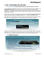
1.1 System Features ........................................................................................................................... 5
1.2 Technical Specifications .............................................................................................................. 6
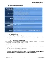
1.3 Hardware ........................................................................................................................................ 6
1.3.1 Physical Connections ............................................................................................................ 6
1.3.2 Desktop or Rack Mount ......................................................................................................... 6
1.3.3 Cooling ..................................................................................................................................... 7
1.3.4 Hot Swappable Power Supplies ........................................................................................... 7
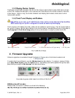
1.3.5 Display Rocker Switch ........................................................................................................... 8
1.3.6 Front Panel Display and Buttons .......................................................................................... 8
2. FIRMWARE UPGRADES ......................................................................................................................... 8
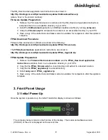
3. FRONT PANEL USAGE ........................................................................................................................... 9
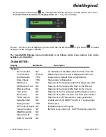
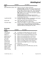
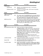
3.1 Initial Power-Up ............................................................................................................................. 9
3.2 Saving Changes ..........................................................................................................................13
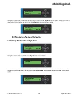
3.3 Restoring Factory Defaults ........................................................................................................14
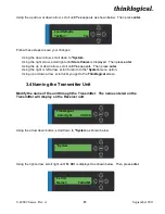
3.4 Naming the Transmitter Unit .....................................................................................................15
4. REGULATORY & SAFETY COMPLIANCE ...........................................................................................16
4.1 Safety Requirements ..................................................................................................................16
4.1.1 Symbols Found on the Product .........................................................................................17
4.1.2 Regulatory Compliance .......................................................................................................17
North America ..........................................................................................................................17
Australia & New Zealand ........................................................................................................17
European Union ......................................................................................................................17
Declaration of Conformity ..................................................................................................17
4.1.3 Standards with Which the Products Comply ....................................................................17
4.2 Supplementary Information .......................................................................................................18
4.2.1 Product Serial Number ........................................................................................................19
4.2.2 Connection to the Product ..................................................................................................19
5. HOW TO CONTACT US .........................................................................................................................19
5.1 Customer Support ......................................................................................................................19
Website ........................................................................................................................................19
Email ............................................................................................................................................20
Telephone ....................................................................................................................................20
Fax ................................................................................................................................................20
5.2 Product Support ..........................................................................................................................20
5.2.1 Warranty ...............................................................................................................................20
5.2.2 Return Authorization ...........................................................................................................21
Our Address ..........................................................................................................................21
APPENDIX A: VelocityKVM T-Series Ordering Information ..................................................................22
APPENDIX B: Thinklogical KVM Extenders- Theory of Operation .......................................................23


