


THCV235_THCV236_Rev.3.40_E
Copyright
©
2016 THine Electronics, Inc.
THine Electronics, Inc.
33/68
Security E
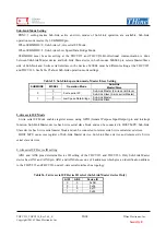
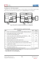
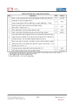
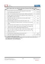
Table 31.
Remote side 2-wire serial slave register Read Procedure for 8bit register address
Step
Description
R/W
Address
1
Set slave address of remote side 2-wire serial slave device (Low-order 7bits),
and enable this address (High-order 1bit).
W 0x04-0x0B
2
Write 1 or 0 and clear(auto clear) access status register (2WIRE_ACS_END_INT).
W
0x02 bit7
3
Set slave address of access target 2-wire serial slave (choose the value set in
0x04-0x0B[6:0]), and set 0 to 0x20 bit7.
W 0x20
4
Set the byte number read from remote side 2-wire serial slave(Max 16byte).
(Byte number = register value + 1)
W 0x22
5
Set the start address of remote side 2-wire serial slave register to read.
W
0x24
6
Write 1 to RD_START_8B. (Start read access to remote side 2-wire serial slave
register)
W 0x26
(*1)
7
(*2)
2-wire serial slave of Sub-Link Master perform clock stretching until Sub-Link Slave
register access is completed. When read access is completed, SCL is released and
read data is stored in Sub-Link Master register (Address 0x10-0x1F).
- -
7
(*3)
When read access is completed, read data is stored in Sub-Link Master register
(Address 0x10-0x1F) and 2WIRE_ACS_END_INT register value become 1 and
interrupt occurs (INT=H
→
L).
- -
8
If read access was normally ended, read value should be “0x1”.
R
0x02
9
HOST MPU read data stored in Sub-Link Master register.
R
0x10-0x1F
10
Repeat from step2 to step10 if needed.
-
-
*1 It’s Prohibit that HOST MPU start access to Sub-Link Slave or remote 2-wire serial slave before the previous access to
Sub-Link Slave or remote side 2-wire serial slave is completed.
*2 When 2WIRE_MODE = 00 (Clock Stretching Mode)
*3 When 2WIRE_MODE = 01 (No Clock Stretching Mode)


