background image


Page 25 


Installation, use and maintenance guide 


SlimQuadro Idra 14 


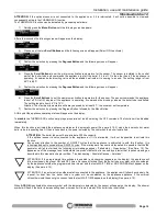
THERMO ACS 

Enables you to activate control of a boiler (if installed) for domestic hot water assigning absolute priority 
to the boiler requirements before replenishing the system. 
This screen only appears if the

 optional sensor is connected to the appliance (See para. 6.9) 

 
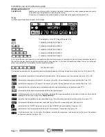
Display 
The following information can appear on the display: 


The appliance is in the OFF stage (See para. 6.9).


1° MANUAL OPERATING POWER 
 
2° MANUAL OPERATING POWER 
 
3° MANUAL OPERATING POWER


4° MANUAL OPERATING POWER 
 
5° MANUAL OPERATING POWER 
 

In this mode the user can choose to run the appliance from the minimum power (therefore with the minimum pellet consumption) to 
the  maximum  power  (therefore  with  the  maximum  pellet  consumption).  In  this  case  the  appliance  always  runs  at  the  set  power 
without any modulation in accordance with the target temperature. 


  AUTOMATIC LEVEL 

 
The appliance modulates the the operating power automatically based on the target temperature set by the user. (See para. 6.10), 


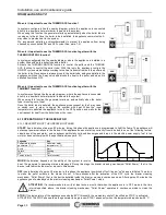
Indicates the temperature of the domestic hot water boiler, if the optional sensor is connected. (See para. 6.7 or 6.9) 


Indicates the temperature of Sensor S1 for control of a puffer, if the optional sensor is connected. (See Para. 6.6) 


Indicates the temperature of Sensor S2 for control of a puffer, if the optional sensor is connected. (See Para. 6.6) 


Indicates that the circulation pump is activated when the water temperature in the boiler exceeds 61°C.


Indicates the boiler water temperature detected by the thermocouple.


The thermometer icon, on the left of the display, indicates the target temperature for the water in the boiler, which can be 
adjusted by the user by means of the 

Degrees Button. 


Indicates  that the appliance has been switched on by the contact of an external chronothermostat. (See para. 7.2) 


Indicates that the appliance has been connected to a puffer which is requesting heat. (See para. 6.6) 


Indicates that the ON/OFF programming set through CHRONO has been enabled. (See para. 6.4) 
 
Indicates the room temperature detected by the thermocouple, if connected. (See para. 6.8) 
 
The thermometer icon, on the right of the display, indicates the target room temperature set by the user if the optional 
sensor is connected. (See para. 6.8) 


Содержание SlimQuadro Idra 14

Страница 1: ......

Страница 2: ...LS 20 5 4 EXAMPLE OF HYDRAULIC DIAGRAM WITH BOILER COILS AND HEATING SYSTEM 21 5 5 HYDRAULIC DIAGRAM WITH THERMOCELL OR THERMOPUFFER ADDITIONAL THERMOPUFFER HIGH TEMPERATURE HEATING AND LOW TEMPERATURE HEATING 22 5 6 INSTRUCTIONS FOR EXECUTING THE HYDRAULIC SYSTEM CLOSED EXPANSION TANK 23 6 USE OF THE APPLIANCE 24 6 1 DESCRIPTION OF THE CONTROL PANEL 24 6 2 DESCRIPTION OF THE POWER PANEL 26 6 3 DA...

Страница 3: ...REWORD 42 9 2 ROOM VENTILATION 42 9 2 1 VENTILATION FROM ADJOINING ROOMS 42 9 2 2 SINGLE OR MULTIPLE VENTILATION DUCTING 42 9 3 SMOKE OUTLET 43 9 3 1 CHIMNEY TYPES 43 9 3 2 FLUE OUTLET FLUE SYSTEM COMPONENTS 43 9 3 3 CONTROLS PRIOR TO INSTALLING THE APPLIANCE 44 10 ALARMS 46 11 ELECTRICAL WIRING 47 12 INFORMATION FOR THE SKILLED TECHNICIAN 48 12 1 MAIN COMPONENTS AND THEIR POSITION 48 12 2 GUIDELI...

Страница 4: ...aspongono le seguenti Direttive 2004 108 CE Direttiva EMC 2006 95 CE Direttiva Bassa Tensione 2011 65 EU Direttiva RoHS 2 is in accordance with the following Directives 2004 108 EC Directive EMC Directive 2006 95 EC Directive Low Voltage Directive 2011 65 EU Directive RoHS 2 e che sono state applicate tutte le norme e o specifiche tecniche di seguito indicate and that all the following standards h...

Страница 5: ...iscaldamento domestico con acqua alimentato a pellet di legno Residential space heating appliance with water fired by wood pellets 4 Nome denominazione commerciale registrata o marchio registrato e indirizzo del fabbricante ai sensi dell articolo 11 paragrafo 5 Name registered trade name or registered trade mark and contact address of the manufacturer as required pursuant Article 11 5 THERMOROSSI ...

Страница 6: ...erating pressure 2 5 bar Temperatura fumi a potenza termica nominale Flue gas temperature at nominal heat output T 124 C Resistenza meccanica per sopportare un camino una canna fumaria Mechanical resistance to carry a chimney flue NPD Nessuna Prestazione Determinata Potenza termica nominale Nominal heat output 13 33 kW Potenza termica resa in ambiente Room heating output 1 46 kW Potenza termica ce...

Страница 7: ...acturer s responsibility pursuant to Italian Decree no 224 of the President of the Republic of 24 05 1988 art 6 b It is recommended to keep this manual in a safe place that is easily accessible to all users if the manual is lost or deteriorated contact the manufacturer for a replacement copy If the appliance is sold or transferred to another user ensure that the manual is handed over with it Therm...

Страница 8: ...liance lighting must occur automatically as intended and described in this installation use and maintenance booklet consequently it is also strictly forbidden to feed pellets or any other material into the brazier Do not place non heat resistant or inflammable or combustible objects in the vicinity of the appliance keep them at a suitable distance Do not place wet clothing to dry on the appliance ...

Страница 9: ... Min water return temperature C 55 Smoke flow at rated power Kg sec 9 6 Smoke flow at reduced power Kg sec 5 5 Efficiency at rated power 93 27 Efficiency at reduced power 95 48 CO concentration in exhaust gas with 13 O2 at rated power mg m 61 5 CO concentration in exhaust gas with 13 O2 at reduced power mg m 143 7 Power supply voltage and frequency 230 V 50 Hz Max electrical consumption W 340 Mini...

Страница 10: ...EZZA 1 2 F SAFETY VALVE 1 2 F RITORNO 3 4 F RETURN 3 4 F MANDATA 3 4 F DELIVERY 3 4 F CARICO SCARICO 3 4 M INLET OUTLET 3 4 M O 80 FUM I 484 84 908 84 600 1109 989 416 MANDATA 3 4 F VALVOLA SICUREZZA 1 2 F RITORNO 3 4 F CARICO SCARICO 3 4 M 295 195 256 189 110 492 190 908 140 314 138 416 146 5 O 80 FUMI ...

Страница 11: ...also create dangerous situations Do not use the appliance as an incinerator at the risk of voiding the warranty 3 3 THE FEEDBOX The feedbox is situated in the top part of the appliance Figure 1 The load capacity specified in the technical data can vary according to the specific weight of the pellets Take special care when loading the tank as the screw feeder at its base is in motion Take care when...

Страница 12: ... Control panel E Combustion air exhaust tube S Spiral tube scraper lever F Smoke exhaust pressure switch T Ash pan G Safety thermostat 100 C U Combustion chamber Patented burner H Pellet loading motor W 3 4 fill drain tap I Pellet tank X Y Plant water return 1 2 pressure safety valve 3000 mbar J Main switch K Plant water delivery AD Smoke temperature sensor L Electronic power board AC Expansion ta...

Страница 13: ...in Article 5 of Ministerial Decree n 37 22 January 2008 d References to existing partial or previous declarations of conformity e g electrical wiring e Copy of the certificate of recognition of the professional technical qualifications These documents must by law be kept together with the use and maintenance booklet The customer is responsible for verifying directly or indirectly that the installa...

Страница 14: ...y placing it in an inclined position and using the locators A indicated in Figure 1 When the edges of the glass abut the locators A delicately place the entire surface of the pane with the applied silicone and exert uniform pressure with your hands over the whole surface while making sure that the pane remains aligned in position Repeat this procedure for all the glass panes After checking that th...

Страница 15: ...is attached to the stove see Figure 4 4 6 WALL MOUNT INSTALLATION The appliance is supplied standard with a wall mount bracket To install the appliance on the wall firstly remove the left right and front panels see instructions in paragraph 4 3 Remove the bracket A by undoing the two screws B which can be accessed by releasing the central cover of the compartment C For instructions on how to faste...

Страница 16: ...DETAIL MANDATA IMPIANTO PLANT DELIVERY USCITA FUMI SMOKE OUTLET RITORNO IMPIANTO PLANT RETURN CARICO SCARICO IMPIANTO SYSTEM INLET OUTLET A DETTAGLIO D Figura 7 Staffa A Viti B Vano C B DETTAGLIO C 401 552 452 47 295 256 190 145 596 405 475 414 190 858 1037 MANDATA IMPIANTO USCITA FUMI RITORNO IMPIANTO CARICO SCARICO IMPIANTO O 60 240 Presa aria ...

Страница 17: ...SCHARGE CONNECTIONS USE FLEXIBLE TUBES HAVING A LENGTH OF AT LEAST 70 CM TO FACILITATE MOVING THE APPLIANCE FOR MAINTENANCE ATTENTION A CONNECTION MUST BE MADE BETWEEN THE SAFETY VALVE AND THE OUTLET TO PREVENT DAMAGING MATERIALS SURROUNDING THE APPLIANCE WHEN THE VALVE IS ACTIVATED ATTENTION To avoid continual startups and shut offs the size of the plant must be such as to guarantee power absorpt...

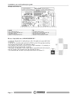
Страница 18: ...OSTAT MODEM terminal free contact COM NO see para 7 that allows the machine to be shut off via an external contact and therefore also restarted This ensures that the generator only activates if there is a real request for heat from the zone in which the chronothermostat is installed Several parallel connected room temperature thermostats can be installed in the CHRONOTHERMOSTAT MODEM This will ens...

Страница 19: ...ter mains for make up ATTENTION it is mandatory to earth the generator If this instruction is not observed serious damage which is not covered by warranty will result to the body of the appliance Have a skilled electrician check the earthing There must be no electric potential Volt between the generator earth and the plant s real earth earth plate To prevent electrochemical corrosion of the applia...

Страница 20: ...mperature that is the temperature set in the generator The boiler tubes can be installed on the water return circuit It is recommended to install a water softener in the domestic water system in order to maintain the boiler at its peak efficiency ATTENTION it is mandatory to earth the generator If this instruction is not observed serious damage which is not covered by warranty will result to the b...

Страница 21: ...orbing all the power that the generator is capable of delivering If this rule is not observed the generator could raise the water temperature to such a point as to activate the safety limit thermostat which stops the fuel from dropping into the burner and therefore forces the appliance to shut off The installer is required to install a valve that switches over to the system powered by the stove s ...

Страница 22: ...ystem ATTENTION the preload pressure of the expansion tank must be greater than the plant pressure for an expansion tank preloaded to 2 bar the plant must be loaded to a pressure that does not exceed 1 5 bar ATTENTION The Thermocell is only fitted with a connection to 230V 50Hz power line The settings of Sensor S1 and Sensor S2 must only be controlled by the appliance See Par 6 6 Connect the two s...

Страница 23: ...ation of conformance in accordance with Ministerial Decree n 37 of 22 January 2008 The generator is already supplied with the following safety devices on board a closed expansion tank for generator protection only b ordinary safety valve 3 bar not I S P E S L approved c an automatic reset temperature limiting device This is an automatic adjustment device that interrupts the fuel supply to the gene...

Страница 24: ...ead outs and functions promptly available The main feature of the panel is the all automatic management of the appliance The controls and the various displays are described below Flame button Pressing this button when the appliance is off activates the START sequence See Para 6 10 sets the operating power in the WORK mode See Para 6 10 or shuts off the appliance by activating the OFF sequence See ...

Страница 25: ... Indicates the temperature of the domestic hot water boiler if the optional sensor is connected See para 6 7 or 6 9 Indicates the temperature of Sensor S1 for control of a puffer if the optional sensor is connected See Para 6 6 Indicates the temperature of Sensor S2 for control of a puffer if the optional sensor is connected See Para 6 6 Indicates that the circulation pump is activated when the wa...

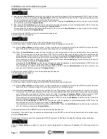
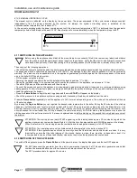
Страница 26: ...section while the selected day of the week remains framed 4 Press the Scroll Buttons to change the hour Once you have set the hour confirm the value by pressing the Degrees Button Once confirmed the selector shifts to the minutes section Press the Scroll Buttons to set the minutes To confirm press the Degrees Button Once confirmed the date and time setting screen closes automatically and the initi...

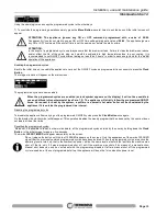
Страница 27: ... the hour at which you wish the appliance to shut off automatically OFF2 Once the hour has been set confirm the value by pressing the Degrees Button Once confirmed the selector shifts to the minute section of OFF2 Press the Scroll Buttons to set the minutes for the second shut off Confirm by pressing the Degrees Button At this point the second ON OFF cycle for the selected day has been set The fol...

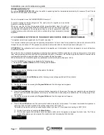
Страница 28: ...se an additional chronothermostat see Para 7 2 The appliance will strictly follow the programmed ON OFF times No request for heat by the system a puffer or a domestic hot water boiler will be considered by the appliance if it is outside the programmed time interval Disabling the programmed cycles To disable the appliance from carrying out the programmed ON OFF cycles press the Clock Button once ag...

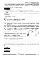
Страница 29: ... over 2 mm water column 20 Pascal The pellet consumption value remains unchanged regardless of the selected operating level These variations will only change the rotation of the smoke suction unit in the WORK stage see Para 6 10 all the other stages will not undergo any changes Select the required Level by acting as follows 1 Press the Menu Button three times quickly and the following box will app...

Страница 30: ...the OFF command The function will be disabled immediately ATTENTION it is advisable to set the action temperature for sensors S1 and S2 as indicated in the hydraulic diagrams in this manual Pay special attention to the number of ON OFF cycles that the appliance is subjected to with this function It is recommended not to exceed three ON OFF cycles If the startups are frequent and repeated it is pos...

Страница 31: ...r tube and ignores requests for heat from the system and the puffer if installed This function is particularly useful in summer when only domestic hot water is required without having to supply the heating system When this function is activated the appliance operates only at automatic power See para 6 10 3 The ACS SUMMER function can be activated in the following way 1 Quickly press the Menu Butto...

Страница 32: ...IT TIME or NO PROGRAM will appear on the display See Para 6 10 ATTENTION If an external chronothermostat is connected to the appliance the appliance will follow it exclusively No request for heat from the puffer will be considered by the appliance if the external chronothermostat does not give consent and the text WAIT TIME appears on the display See para 6 10 ATTENTION When ACS SUMMER is set the ...

Страница 33: ...0 ATTENTION If an external chronothermostat is connected to the appliance the appliance will follow it exclusively No request for heat from the room will be considered by the appliance if the external chronothermostat does not give consent and the text WAIT TIME appears on the display See Para 6 10 ATTENTION The appliance controls the room temperature sensor with a 2 C hysteresis so if for example...

Страница 34: ...ion will be disabled immediately When this function is activated the appliance operates at the automatic power See para 6 10 3 when the domestic hot water boiler tube is requesting heat it then reverts back to the power selected by the user when the boiler is satisfied ATTENTION The boiler tube must have at least a 300 litre capacity If the optional sensor is not connected to the appliance or if i...

Страница 35: ...e turns to the OFF position and waits for the next request for heat from the boiler tube or the room 6 10 OPERATION OF THE GENERATOR 6 10 1 DESCRIPTION OF THE OPERATING STAGES START has a duration of approx 20 minutes during this phase the appliance is programmed to light the flame The appliance will not accept power variations in the firebox If the appliance does not start up correctly it could b...

Страница 36: ...l for the components of the appliance and seriously affect their duration 6 10 3 AUTOMATIC CYCLE In the automatic cycle the appliance expresses its maximum operating flexibility by optimising the fuel consumption To activate the AUTO cycle select the power bars up to the sixth bar containing the text AUTO During the AUTO cycle the appliance self regulates the combustion function according to the t...

Страница 37: ... the hopper Press the Flame Button to begin the start up phase and the word START will appear on the display Check the pressure in the appliance system once again and if necessary bleed any air bubbles from the valve Press the Flame button repeatedly to set the appliance in AUTO or manual operating mode The mode will be activated at the end of the start up phase By pressing the Degrees Button you ...

Страница 38: ...wer bar will flash on the display any manual power change will be disabled When the room temperature drops the thermostat opens the contact and the appliance returns to its original position in terms of thermal power ATTENTION N C Normally Closed contacts must be used for the connection to the additional room temperature thermostat Do not power the contacts with mains voltage as this would serious...

Страница 39: ...the nearby diagram where the appliance is connected directly to the system In this case the chronothermostat controls the ON OFF cycles of the appliance according to the programmed time bands or the temperature setting If the dwelling is fitted with zone valves with this type of installation it is mandatory to deactivate the valves by opening them completely Consequently the dissipation of heat at...

Страница 40: ... the top smoke circuit compartment Figure 6 To access the compartment pull with force the cover A to release it undo the wing nuts B and unscrew the turbulator shaker knob C Remove the cover D making sure you do not damage its insulation Attention take special care when handling the cover and avoid knocking or dropping it Accidental breakages are not covered by warranty Attention to guarantee corr...

Страница 41: ...Page 41 Installation use and maintenance guide SlimQuadro Idra 14 Legenda Key Figura Figure PelletPower Figura 1 Figura 2 Figura 3 C1 Figura 4 C2 Figura 5 C3 Figura 6 A B B C D ...

Страница 42: ...flow can also be obtained from an adjoining room as long as the adjoining room is equipped with direct ventilation in compliance with the paragraphs described above only appliances connected to the exhaust pipe are installed in the room that is ventilated the adjoining room is not used as a bedroom or a common area of the building the adjacent room is not a room with a fire hazard such as storage ...

Страница 43: ...risk of creating condensation 9 3 1 CHIMNEY TYPES The following types of chimneys constructed as described are possible System Chimney installed using a combination of compatible components flue liner insulation outer casing etc constructed or specified by a single manufacturer and CE certified in accordance with the applicable standard Composite chimney Chimney installed or constructed on site us...

Страница 44: ...h inspection cap and suitable supporting brackets If the flue outlet is too big it is necessary to insert a stainless steel or porcelain coated steel tube with a diameter not exceeding 150mm Seal area where the inlet and outlet part of the smoke exhaust meets the wall It is strictly forbidden to apply mesh to the end of the outlet tube as it could cause the appliance to malfunction If LEGENDA KEY ...

Страница 45: ...ttings sealed with red silicone resistant to 350 C The outer casing of the tube must be made with insulating material mineral wool ceramic fiber or use pre insulated tubing THE FLUE OUTLET MUST BE USED ONLY FOR THE APPLIANCE It must be possible to inspect and remove all the smoke tube sections for clean out purposes ATTENTION if the flue outlet is not sufficiently insulated and or if it is too lon...

Страница 46: ...switched off then on by turning the switch 0 1 located on the power panel Before restarting the appliance check for any irregularities such as blocked flue outlet open firebox door Do not start up the appliance until the problem has been identified and solved It is mandatory to empty and clean the brazier before repeating the START phase This appears when the water temperature in the appliance exc...

Страница 47: ...o LED Feeder gearmotor Pressostato fumi Smoke pressure switch Valvola tre vie Three way valve Motoriduttore pulizia Cleaning gearmotor Circolatore Circulating pump Termostato riarmo Reset thermostat Circolatore ausiliario Auxiliary circulating pump Aspiratore fumi Smoke suction unit Resistenza accensione Lighting heater 1 1 1 2 Morsettiera CN 2 Morsettiera CN 7 1 2 2 3 4 5 6 7 8 9 10 1 2 3 4 5 6 7...

Страница 48: ...emperature reactivate the appliance by unscrewing the plastic cover of the thermostat and press the button the temperature of the appliance must have dropped considerably SPARK PLUG It is activated in the START phase It heats the incoming air to the brazier up to 800 C which promotes the first combustion of the pellets in the brazier AUTOMATIC PURGE VALVE The function of this valve is to eliminate...

Страница 49: ...would obviously cause the appliance to malfunction Keep the appliance clean and check the burner as described in these instructions Clean the smoke outlet regularly Use good quality pellets use of poor pellets can result in up to 50 less efficiency The pellets must be stored in a well ventilated dry place The generator door must always remain closed during normal operation Do not touch hot outer s...

Страница 50: ...LETS THE APPLIANCE LEAKS SMOKE INTO THE ROOM OCCURS THE FIRST TIME THE APPLIANCE IS SWITCHED ON AS THE SILICONE PAINT IS BEING BAKED RUN THE APPLIANCE AT HIGH POWER LEVELS FOR A FEW DAYS THE SMOKE EXHAUST IS NOT SEALED CORRECTLY CHECK THE TIGHTNESS OF THE FLUE OUTLET PARTICULARLY THE CONDITION OF THE EXHASUT PIPES AND THE TIGHTNESS OF THE SEALS IF THE APPLIANCE STARTS TO SMOKE AFTER 25 MINUTES DIR...

Страница 51: ...AUSTED REPLACE THE BATTERY THE HOURLY PROGRAM IS NOT COMPLIED WITH THE USER HAS NOT ENABLED IT PRESS THE CLOCK BUTTON TO ENABLE IT AS INSTRUCTED IN THIS USE AND MAINTENANCE GUIDE THE BUFFER BATTERY INSTALLED IN THE CONTROL PANEL IS EXHAUSTED REPLACE THE BATTERY AN ERROR HAS BEEN MADE WITHIN THE PROGRAMMED CYCLE A SHUT OFF TIME HAS BEEN SET BEFORE THE START TIME VERIFY THE TIMES SET IN THE CHRONO S...

Страница 52: ...TRO 70018084 FIANCO DESTRO 60013860 Vetro DX basso SX alto bianco 60013861 Vetro DX basso SX alto rosso 60013862 Vetro DX basso SX alto nero 60013863 Vetro SX basso DX alto bianco 60013864 Vetro SX basso DX alto rosso 60013865 Vetro SX basso DX alto nero 70018107 Pannello frontale senza vetri 70018087 70018088 70018086 70018114 Sportellino completo ...

Страница 53: ...Pressostato 70018806 60011656 Interruttore 0 1 60007462 Termostato riarmo 60004921 Pozzetto 70015296 BASAMENTO 60013639 Res accensione 70016450 CASSETTO 70018881 VASO 60012595 60012583 70015962 70016443 COMPLETA 70016445 GUARNIZIONE 70016276 70016474 60012594 60012583 60011693 70016441 70016453 70016473 70016463 70016344 Aspiratore 70016436 Isolazione 70015966 Coperchio completo 70016250 Guarniz 7...

Страница 54: ...0013891 70015947 70015221 Vetro 70015873 Protezione chiusura 70016046 Vite 70015872 Chiusura 70015894 Porta completa 70014154F Porta in ghisa 70014780 Profilo laterale 60013919 Treccia D 8 60010336 Treccia D 5 70015112 Cerniera 60011215 Dado ribassato 60014016 60013635 70017793 70017794 70018770 70015952 70016477 Leverismo completo 70017798 70018245 Braciere completo ...

Страница 55: ...chio completo Complete cover Insolazione Insulation MANIGLIA HANDLE Pannello comandi Control panel Motoriduttore Gearmotor Bussola fissaggio motore Motor fixing bush Frangia Flange Guarnizione Gasket Gruppo alimentazione pellet Pellet feeder unit Boccola Bush Pressostato Pressure switch Circuitazione completa Complete circuits Scheda potenza Power board Interruttore 0 1 Switch 0 1 Termostato riarm...

Страница 56: ...Page 56 Installation use and maintenance guide SlimQuadro Idra 14 NOTES ...

Страница 57: ...Page 57 Installation use and maintenance guide SlimQuadro Idra 14 NOTES ...

Страница 58: ...Page 58 Installation use and maintenance guide SlimQuadro Idra 14 NOTES ...

Отзывы: