background image

Operation 

Settings 

Thermo Scientific 

43iQHL Instruction Manual     

3-61


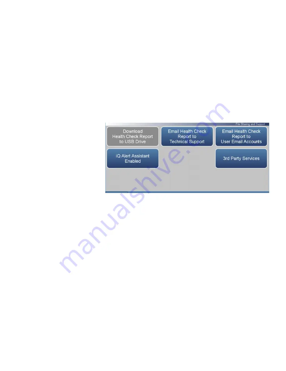
The File Sharing and Support screen allows the user to send health check 

report files to Thermo Fisher Scientific technical support or user emails. 

The Health Report file includes: Status and Alarms, PM Alerts, Activity 

Log, Service Database, Cal History, and Data Log (last 24 hours). 

Note  

To create email list, go to Settings>User Contact Information. To 

configure email, go to Settings>Communications>Email Server 

(SMTP). 


Home Screen>Settings>Health Check>File Sharing and Support


The File Sharing and Support screen contains the following information: 


Download Health Check Report to USB Drive:

 Sends the health report to 

USB drive. 


Email Health Check Report File to Technical Support:

 Sends the health 

report file to technical support and the customer email addresses via 

email. 


Email Health Check Report to Personal Account:

 Sends the health report 

file to a personal account via email. 


iQ Alert Assistant:

 With the iQ Alert Assistant enabled, the instrument 

will email Thermo Scientific Technical Support the health check report 

after each event. After each maintenance alert or predictive diagnostic 

alert, Customer Service will produce a quote for the components that 

require service. This quote will get emailed to the email addresses that 

have been entered into the “User Contact Information” menu. 


3

rd

 Party Services:

 The 3

rd

 party services feature is a paid subscription, 

which allows a service provider to enable or disable automated email 

notifications when an alarm or alert is triggered. 

File Sharing and Support 

Содержание 43iQHL

Страница 1: ...43iQHL Instruction Manual High Level Sulfur Dioxide Analyzer 119015 00 1Apr2022...

Страница 2: ......

Страница 3: ...splay 3 1 Main Menus and Keypads 3 5 Numeric Keypad 3 6 Alphanumeric Keypad 3 7 Calibration 3 9 Calibrate Background 3 11 Calibrate Span Coefficient 3 12 Zero Span Schedule 3 14 Advanced Calibration 3...

Страница 4: ...unications 3 80 Wired TCP DHCP 3 82 Serial RS 232 485 3 84 Analog I O 3 85 Digital I O 3 86 Email Server SMTP 3 87 Bayern Hessen Settings 3 88 Ethernet Protocol Selection 3 89 Instrument Settings 3 90...

Страница 5: ...Span Coefficient 4 12 Reset Bkg to 0 000 and Span Coef to 1 000 4 13 Multipoint Calibration 4 14 High and Low Multipoint Calibration 4 16 Calibration Frequency 4 16 Zero Span Schedule 4 17 Next Time 4...

Страница 6: ...ical Bench Assembly Removal 7 32 Photomultiplier Tube PMT Replacement 7 34 Flasher Pack Replacement 7 36 Flasher Pack Lamp Replacement 7 37 Photo Lamp Detector Board Replacement 7 38 Kicker Assembly R...

Страница 7: ...s 9 5 Analog Output Calibration 9 6 Analog Output Zero Calibration 9 7 Analog Output Full Scale Calibration 9 9 Digital I O Board 9 11 Digital Inputs 9 11 Digital Relay Switches 9 13 Valve Driver Outp...

Страница 8: ......

Страница 9: ...cificity and long term stability The iQ Series Instrument Platform is a smart environmental monitoring solution for ambient and source gas analysis that affords greater control over instrument perform...

Страница 10: ...ter keyboard or mouse The iQ Series GUI runs on a 7 color touchscreen display The GUI is highly flexible and can be customized to enable a tailored experience to simplify daily operations Custom desig...

Страница 11: ...orescence chamber A photodetector located at the back of the fluorescence chamber continuously monitors the pulsating UV light source and is connected to a circuit that compensates for fluctuations in...

Страница 12: ...Introduction 43iQHL Principle of Operation 1 4 43iQHL Instruction Manual Thermo Scientific Figure 1 2 43iQHL Flow Schematic Figure 1 3 43iQHL Flow Schematic with Zero Span...

Страница 13: ...110 sec 60 second averaging time 320 sec 300 second averaging time Linearity 1 full scale Flow Rate 0 7 lpm standard Interferences EPA levels Less than lower detectable limit except for the following...

Страница 14: ...Scientific Serial Ports 1 RS 232 485 port 1 RS 485 External Accessory port Other Ports 3 Full Speed USB ports one in front two in rear 1 Gigabit Ethernet port Communication Protocols MODBUS Streaming...

Страница 15: ...Introduction Dimensions Thermo Scientific 43iQHL Instruction Manual 1 7 Figure 1 4 Bench Mount Assembly dimensions in inches mm Dimensions...

Страница 16: ...Introduction Dimensions 1 8 43iQHL Instruction Manual Thermo Scientific Figure 1 5 Rack Mount Assembly dimensions in inches mm...

Страница 17: ...Introduction Dimensions Thermo Scientific 43iQHL Instruction Manual 1 9 Figure 1 6 Rack Mount Requirements Figure 1 7 Rack Requirements Part 2...

Страница 18: ......

Страница 19: ...ng container when you receive the instrument notify the carrier immediately and hold for inspection The carrier is responsible for any damage incurred during shipment Use the following procedure to un...

Страница 20: ...the cover Equipment required Phillips screwdriver 2 1 Unfasten the four 8 32 screws securing the cover shipping screws 2 Press in both latches located on top cover and hold while pulling up to remove...

Страница 21: ...rument can be installed in the following configurations Bench Mount Rack Mount Positioned on bench includes installing feet See Figure 2 2 Equipment required Slot drive 5 16 inch 1 Fasten feet in posi...

Страница 22: ...required Phillips drive 2 1 Start by gripping from the top corners of the front panel and pull outwards Figure 2 3 Removing the Front Panel 2 Unfasten the four 8 32 pan head screws 3 Slide ears outwa...

Страница 23: ...Installation and Setup Mounting Options Thermo Scientific 43iQHL Instruction Manual 2 5 Figure 2 4 Installing Ears and Handles...

Страница 24: ...ample filter is used all calibrations and span checks must be performed through the filter The filter element should be replaced regularly to prevent the absorption of SO2 by trapped material on the f...

Страница 25: ...7 5 Plug the instrument into an outlet of the appropriate voltage and frequency The 43iQHL is supplied with a three wire grounding cord Under no circumstances should this grounding system be defeated...

Страница 26: ...displayed on the gas mode button in the title bar and the concentration calculation is turned off To disable warm up go to Settings Configuration 3 Set instrument parameters such as operating ranges a...

Страница 27: ...ser Interface located in the middle is where the Home Screen and all other screens are accessed The Home Screen has three Main Menu buttons located on the left side which include Calibration Data and...

Страница 28: ...Operation Instrument Display 3 2 43iQHL Instruction Manual Thermo Scientific Home Screen dual or auto range mode Title Bar User Interface Status Bar...

Страница 29: ...time status and alarms also predictive diagnostics and maintenance history Contains controls for operating the instrument communications and sets instrument options Concentration When in single mode...

Страница 30: ...Operation Instrument Display 3 4 43iQHL Instruction Manual Thermo Scientific Thermo Scientific Information button Shows contact information...

Страница 31: ...e Setting Gas Mode Gas Units Dilution Ratio Advanced Measurement Optical Bench Settings Flash Lamp Optical Span Test Extended Ranges Compensation Pressure Calibration Instrument Settings Display Setup...

Страница 32: ...ch as for flow rates temperatures or pressures the keypad screen will automatically display Initially the box above the keypad will display the current value Enter a new value using the keypad and the...

Страница 33: ...tomatically display Initially the box above the keypad will display the current value Enter a new value using the keypad and then select the Enter button to set the new value or press the Cancel butto...

Страница 34: ...Operation Instrument Display 3 8 43iQHL Instruction Manual Thermo Scientific...

Страница 35: ...ch range to be calibrated separately This is necessary if the two ranges used are not close to one another For example a low SO2 range of 10 ppm and a high SO2 range of 1000 ppm For more information a...

Страница 36: ...efficient Sets the low range span coefficient when in dual or auto range mode Zero Span Schedule Programs the instrument to perform fully automated zero and span checks or adjustments Advanced Calibra...

Страница 37: ...e each time input gas is changed and set the averaging time to 300 second averaging Home Screen Calibration Calibrate Background The Calibrate Background screen contains the following information Targ...

Страница 38: ...dicate the calibration of the high or low coefficient The Calibrate High Range Span Coefficient and Calibrate Low Range Span Coefficient screens function the same way It is important to note the avera...

Страница 39: ...de Current Span Coefficient Read only Displays the current instrument span coefficient Current High Range Span Coefficient Read only Displays the current instrument high range span coefficient Current...

Страница 40: ...n schedule Enabled or Disabled Next Time Allows the user to view and set the initial date and time 24 hour format of the zero span schedule Period Defines the period or interval between zero span chec...

Страница 41: ...d value is not updated Span Calibration Toggles Enabled Disabled If enabled span coefficient is calibrated If disabled schedule runs a calibration check only and span coefficient is not updated Zero S...

Страница 42: ...difference between the screens are the words High and Low For more information about range modes see Range Mode Selection on page 3 69 Home Screen Calibration Advanced Calibration single range mode H...

Страница 43: ...ange may be calibrated Three cal points will give the most accurate readings over the entire range Low Range Multipoint Calibration Up to three gas concentrations cal points for low range may be calib...

Страница 44: ...n dual or auto range modes High Range or Low Range buttons are displayed to indicate the calibration of the high or low coefficient Home Screen Calibration Advanced Calibration Manual Calibration sing...

Страница 45: ...user to manually adjust the high range span coefficient when in dual or auto range mode Adjust Low Range Span Coefficient Allows the user to manually adjust the low range span coefficient when in dua...

Страница 46: ...nced Calibration Manual Calibration Adjust Background The Adjust Background screen contains the following information Adjust Background User manually adjusts zero background Adjusted Concentration Rea...

Страница 47: ...nt and Adjust Low Range Span Coefficient screens function the same way Home Screen Calibration Advanced Manual Calibration Adjust Span Coefficient single range mode Home Screen Calibration Advanced Ca...

Страница 48: ...nge concentration based on adjusted high range span coefficient when in dual or auto range mode Adjust Low Range Span Coefficient User manually adjusts low range span coefficient when in dual or auto...

Страница 49: ...Calibration screens function the same way Note Pressing the Multipoint Calibration button responds with It is recommended to calibrate all three points and requires an OK action Home Screen Calibratio...

Страница 50: ...tion 3 24 43iQHL Instruction Manual Thermo Scientific Third Coefficient Read only Value of the third coefficient in the polynomial curve Reset Points to Default Values Resets multipoint coefficients t...

Страница 51: ...ion screens function the same way The customer defines the ranges It is suggested to perform the following calibration points for each range Cal point 1 80 of range Cal point 2 50 or range Cal point 3...

Страница 52: ...Calibration History Note Pressing the Calibration History button responds with Retrieving calibration log data it may take a few seconds The Calibration History screen contains the following informati...

Страница 53: ...llowing information View Data Log Last Hour User views last hour of historical data Table shows most recent data on top View Data Log Last 24 Hours User views 24 hour of historical data Table shows mo...

Страница 54: ...move up and down and the and buttons to move left and right Home Screen Data View Data Log Last Hour Note Pressing the View Data Log Last Hour responds with Retrieving user log data it may take a few...

Страница 55: ...nd down and the and buttons to move left and right Home Screen Data View Data Log Last 24 Hours Note Pressing the View Data Log Last 24 Hours responds with Retrieving user log data it may take a few s...

Страница 56: ...Time Home Screen Data View Data Log User Defined Time Save Data Logging Start Time The View Data Log User Defined Time screen contains the following information Date Sets date of data logging start t...

Страница 57: ...ation Date Sets date of data logging end time Time Sets time of data logging end time Save Data Logging End Time Pressing the Save Data Logging End Time button saves the end time and follows directly...

Страница 58: ...p parameters for data logging and streaming data Home Screen Data Advanced Data Setup The Advanced Data Setup screen contains the following information Data Logging Setup User selects the parameters f...

Страница 59: ...bles to log Period User selects how often data is collected by setting the duration between logged data values Data Treatment Toggles between Average Current Minimum and Maximum When set to average th...

Страница 60: ...tain the same variable selections The list is based on the instrument s configuration Use the and buttons to scroll through the variables Select the variables to log by pressing the corresponding cell...

Страница 61: ...tup The Streaming Data Setup screen contains the following information Select Streaming Variables User selects which variables to stream Period Sets the time between streamed data Show Labels Toggles...

Страница 62: ...tain the same variable selections The list is based on the instrument s configuration Use the and buttons to scroll through the variables Select the variables to log by pressing the corresponding cell...

Страница 63: ...act Thermo Fisher Scientific technical support Measurement Settings Allows the user to setup user preferences as related to the concentration readings Communications Allows the user to communicate wit...

Страница 64: ...contains the following information Status and Alarms Allows the user to view the status and alarm menus Menus are broken down according to modules where the user can view instrument readings setpoints...

Страница 65: ...Health Check Status and Alarms The Status and Alarms screen contains the following information Concentration Displays SO2 concentrations alarms and calibration pass fail status SO2 Bench Displays benc...

Страница 66: ...ng information Across Concentration This column lists items associated with the SO2 concentration Value Displays the current value for each item Low Alarm Displays low alarm for each item High Alarm D...

Страница 67: ...ntific 43iQHL Instruction Manual 3 41 acceptable span check offset compared to the span concentration value Span concentration shows span setpoint Note If both the low alarm and high alarms are set to...

Страница 68: ...associated with the SO2 bench Value Displays the current value for each item Low Alarm Displays low alarm for each item High Alarm Displays high alarm for each item Units Displays units for each item...

Страница 69: ...mmunication status Power Supply Displays OK Fail of power supplies Power supply goes red if any voltages are outside their limits No voltage rows ever get highlighted 3 3V Diagnostic Displays current...

Страница 70: ...ation Across Flow and Pressure This column lists items associated with the flow and pressure module Value Displays the current value for each item Low Alarm Displays low alarm status for each item Hig...

Страница 71: ...if any voltages are outside their limits No voltage rows ever get highlighted 2 5V Diagnostic Displays current voltage readings Alarm limits are not changeable 3 3V Diagnostic Displays current voltag...

Страница 72: ...Across Peripherals Support This column lists items associated with the peripherals support module Value Displays the current value for each item Low Alarm Displays low alarm status for each item High...

Страница 73: ...iagnostic Displays current voltage readings Alarm limits are not changeable 5 0V Diagnostic Displays current voltage readings Alarm limits are not changeable 24V Diagnostic Displays current voltage re...

Страница 74: ...symbol denotes that the device needs to be reset Note Resetting one valve will reset all valves Home Screen Settings Health Check Status and Alarms Valve and Pump Resets The Valve and Pump Resets scr...

Страница 75: ...tains the following information Across Analog IO This column lists items associated with the analog I O Value Displays the current value for each item Low Alarm Displays low alarm status for each item...

Страница 76: ...o voltage rows ever get highlighted 3 3V Diagnostic Displays current voltage readings Alarm limits are not changeable 5 0V Diagnostic Displays current voltage readings Alarm limits are not changeable...

Страница 77: ...he following information Across Digital IO This column lists items associated with the digital I O Value Displays the current value for each item Reset Resets item Low Alarm Displays low alarm status...

Страница 78: ...oes red if any voltages are outside their limits No voltage rows ever get highlighted 3 3V Diagnostic Displays current voltage readings Alarm limits are not changeable 5 0V Diagnostic Displays current...

Страница 79: ...Check Status and Alarms Serial Numbers The Serial Numbers screen contains the following information Instrument Instrument serial number SO2 Bench SO2 bench serial number Flow and Pressure Flow and pr...

Страница 80: ...eshooting time If button is greyed out no maintenance is needed If button is blue maintenance is suggested Note This symbol denotes there is an active maintenance related warning in the module Home Sc...

Страница 81: ...Health Check Maintenance Home Screen Settings Health Check Maintenance Advanced Maintenance The Maintenance screen contains the following information Preventive Maintenance Shows suggested service in...

Страница 82: ...ance The Preventive Maintenance screen contains the following information Across Component Device to be routinely serviced or replaced Interval in Months Expected period of time before a component nee...

Страница 83: ...y Service interval for flash intensity assembly Mirrors Service interval for mirrors Flow System Service interval for the flow system components Capillaries Service interval for capillaries Pump Servi...

Страница 84: ...e diagnostics screen when applicable Home Screen Settings Health Check Maintenance Change Part The Change Part screen contains the following information Select Part User selects part to service from t...

Страница 85: ...he and buttons to move up and down and the and buttons to move left and right Home Screen Settings Health Check Maintenance Maintenance History Note Retrieving maintenance history data it may take a f...

Страница 86: ...ic The Service Tips screen allows the user to XXXX Home Screen Settings Health Check Maintenance Service Tips The Service Tips screen contains the following information Pump Rebuild Video XXXX Step PO...

Страница 87: ...ive Email Health Check Report File to Technical Support Sends the health report file to technical support and the customer email addresses via email Email Health Check Report to Personal Account Sends...

Страница 88: ...ngs Health Check iQ360 Get Started Home Screen Settings Health Check iQ360 Status and Renewal Request The iQ360 screen contains the following information Get Started Allows the user to access the menu...

Страница 89: ...ck iQ360 Get Started The Get Started screen contains the following information Resend Subscription E mail Allows the user to request another subscription passcode if the email was never received Enter...

Страница 90: ...nd Renewal Request The Status and Renewal Request screen contains the following information iQ360 Status Informs the user if the subscription is enabled iQ360 Subscription Expiration Date Informs the...

Страница 91: ...ing buttons will be available Home Screen Settings Measurement Settings single range mode Home Screen Settings Measurement Settings dual or auto range mode The Measurement Settings screen contains the...

Страница 92: ...Low Range Setting Sets the low range concentration for the analog output when in dual or auto range mode Gas Mode User can manually choose sample zero or span mode Gas Units Defines the units in whic...

Страница 93: ...will be the output at each update every 10 seconds Therefore the lower the averaging time the faster the front panel display and analog outputs respond to concentration changes Longer averaging times...

Страница 94: ...les disables high range dynamic filtering when in dual or auto range mode Low Range Dynamic Filtering Enables disables low range dynamic filtering when in dual or auto range mode Averaging Time Sets a...

Страница 95: ...put can be set to output concentrations from 0 to 50 ppm and the high SO2 analog output set to output concentrations from 0 to 100 ppm In addition each SO2 analog output has a span coefficient so that...

Страница 96: ...nge is active the concentration must drop to 85 of the low SO2 range for the low range to become active In addition each SO2 range and analog output has a span coefficient so that each range can be ca...

Страница 97: ...Low displayed to indicate which range is displayed For more information about the dual and auto range modes see Range Mode Selection on page 3 69 Pressing Range Setting High Range Setting or Low Rang...

Страница 98: ...ttings Measurement Settings Gas Mode The Gas Mode screen contains the following information Sample Sets the instrument to measure sample gas Zero Used when calibrating the background of the instrument...

Страница 99: ...standard pressure of 760 mmHg and a standard temperature of 0 C The temperature can be changed in the compensation screen Use the and buttons to select Home Screen Settings Measurement Settings Gas U...

Страница 100: ...tial flash reference Flash Lamp Enables Disables flash lamp Optical Span Test Enables Disables test LED and reads the LED SO2 concentration Extended Ranges Enables Disables extended ranges feature Whe...

Страница 101: ...up and down and the and buttons to move left and right Home Screen Settings Measurement Settings Advanced Measurement Settings Optical Bench Settings Home Screen Settings Measurement Settings Advance...

Страница 102: ...calibration is interrupted and the value does not change Default Values When pressed the default gain for the lamp intensity detector is restored Home Screen Settings Measurement Settings Advanced Me...

Страница 103: ...tion Displays target concentration Calibration Concentration Displays calibration concentration Auto Calibration When pressed the auto calibration process is initiated Please allow up to 5 minutes for...

Страница 104: ...The effects of internal instrument temperature changes on the analyzer s subsystems and output have been empirically determined This empirical data is used to compensate for any changes in temperature...

Страница 105: ...sor Calibration Starts calibration or resets default values Down Sensor 1 3 Reading Under the column labeled Reading current reading of each pressure sensor Atmospheric Sensor 1 3 Under the column lab...

Страница 106: ...tion Communications Board Analog I O Settings for communicating with the instrument through analog I O settings This is only visible if selected in Settings Configuration Analog I O Digital I O Settin...

Страница 107: ...t the instrument should respond with in response to a valid data query DA command Note Refer to the Bayern Hessen Protocol section in the Communications Manual for a detailed description Ethernet Prot...

Страница 108: ...s disabled the static IP address is used Home Screen Settings Communications Wired TCP DHCP with DHCP enabled Home Screen Settings Communications Wired TCP DHCP with DHCP disabled The Wired TCP DHCP s...

Страница 109: ...DHCP is disabled Static Netmask Static Netmask of instrument This is settable when DHCP is disabled Static Gateway Static Gateway of instrument This is settable when DHCP is disabled DNS Server Addres...

Страница 110: ...e Screen Settings Communications Serial RS 232 485 The Serial RS 232 485 screen contains the following information Protocol User selects Streaming Modbus or Bayern Hessen Baud Rate User selectable bau...

Страница 111: ...Analog In Allows the user to view and calibrate voltage inputs from external devices Analog Out Voltage Allows the user to view voltage outputs Analog Out Current Allows the user to view current mA o...

Страница 112: ...Digital I O Home Screen Settings Communications Digital I O The Digital I O screen contains the following information Digital In Allows the user to view digital inputs from external devices Digital Ou...

Страница 113: ...erver SMTP The Email Server SMTP screen contains the following information SMTP Server Address Address of the user s email server From Email Address The email address that goes in the From field in em...

Страница 114: ...tings The Bayern Hessen Settings screen contains the following information Across Number Lists up to 8 registers that can selected by the user Register User selects the measured values to be logged Me...

Страница 115: ...ilize the mobile app and or those communication protocols Press Commit changes button to save selections Yellow buttons indicate that the selection is enabled More than one can be chosen Home Screen S...

Страница 116: ...tings Instrument Settings The Instrument Settings screen contains the following information Display Setup Sets touch screen display settings Alarm Setpoints View and set all available alarm minimum an...

Страница 117: ...r save option Home Screen Settings Instrument Settings Display Setup The Display Setup screen contains the following information Power Save Minutes before screen times out Toggles enable disable Power...

Страница 118: ...d buttons to move up and down and the and buttons to move left and right Home Screen Settings Instrument Settings Alarm Setpoints The Alarm Setpoints screen contains the following information Across V...

Страница 119: ...pan reading offset for calibration and calibration checks This is set with the high alarm only Chamber Temperature Chamber temperature alarm Lamp Intensity Lamp intensity alarm Lamp Voltage Lamp volta...

Страница 120: ...on Manual Thermo Scientific The Language screen allows the user to choose from the following languages Home Screen Settings Instrument Settings Language The Language screen contains the following info...

Страница 121: ...me zone and time server Home Screen Settings Instrument Settings Clock The Clock screen contains the following information Date User sets date Date Format User selects date format Time User sets time...

Страница 122: ...96 43iQHL Instruction Manual Thermo Scientific The Date screen allows the user to choose date Use the and buttons to move left and right to select month and year Home Screen Settings Instrument Setti...

Страница 123: ...the user to choose from the following formats mm dd yyyy or dd mm yyyy Use the and buttons to select Home Screen Settings Instrument Settings Clock Date Format The Date Format screen contains the foll...

Страница 124: ...ntific The Time screen allows the user to choose from the following formats mm dd yyyy or dd mm yyyy Use the and buttons to select Home Screen Settings Instrument Settings Clock Time The Time screen c...

Страница 125: ...nt Settings Clock Time Zone The Time Zone screen contains the following information Date Line West UTC 12 Samoa Time Zone UTC 11 Aleutian Time Zone UTC 10 Alaskan Time Zone UTC 9 Pacific Time Zone UTC...

Страница 126: ...l European Time UTC 1 Eastern European Time UTC 2 Further Eastern European Time UTC 3 Gulf Standard Time UTC 4 Yekaterinburg Time UTC 5 Omsk Time UTC 6 Indochina Time UTC 7 ASEAN Common Time UTC 8 Jap...

Страница 127: ...iodic clock updates Home Screen Settings Instrument Settings Clock Time Server The Time Server screen contains the following information Time Server Enables Disables periodic clock updates from an NTP...

Страница 128: ...ng cells Next press the Commit Changes button to save selections Yellow buttons indicate that the variable is selected More than one can be chosen Home Screen Settings Configuration The Configuration...

Страница 129: ...nly Access The Security Access Levels screen contains the following information Current Security Access Full Access Read only User will be able to change all values Password is needed for full access...

Страница 130: ...hermo Scientific Change Full Access Security Password Full access password can have a blank value or user selected password Change Instrument Password User can change instrument password Reset Instrum...

Страница 131: ...View Only Access The Change Security to View Only Access screen contains the following information Set Access Level to View Only Programs the instrument to be in the view only access level where the...

Страница 132: ...curity Password screen allows the user to set a new password for allowing full access Home Screen Settings Security Access Levels Change Full Access Security Password Home Screen Settings Security Acc...

Страница 133: ...nt security password Continue Proceeds to next screen Enter New Security Access Password User enters new security password Confirm New Security Access Password User confirms new security password for...

Страница 134: ...c The Change Instrument Password screen allows the user to change the instrument password Home Screen Settings Security Access Levels Change Instrument Password Home Screen Settings Security Access Le...

Страница 135: ...t instrument password Continue Proceeds to next screen Enter New Instrument Password User enters new instrument password Confirm New Instrument Password User confirms new instrument password for spell...

Страница 136: ...instrument serial number is 123456789 and the instrument firmware version is 1 6 8 ABCDE where the last five digits are the build number then the default instrument password number will be 1A2B3C4D5E6...

Страница 137: ...e USB port When a USB drive is inserted the user is prompted to enter the password if a password has been set Home Screen Settings USB Drive The USB Drive screen contains the following information Fir...

Страница 138: ...from the USB drive Home Screen Settings USB Drive Firmware Update Via USB Drive The Firmware Update Via USB Drive screen contains the following information Update Firmware User chooses firmware file...

Страница 139: ...won t be recognized Also make sure the USB stick is formatted using the FAT or FAT32 file system 2 Plug a USB flash drive into the data port on the front panel of the unit or into one of the USB ports...

Страница 140: ...on to start the firmware update process 5 Press the Update Firmware button 6 The on screen instructions will prompt the user to select the firmware update file and display what it is doing at each ste...

Страница 141: ...not power off the instrument while the firmware update is in progress 8 The instrument should reboot automatically and should have the new firmware installed To check that the firmware was installed...

Страница 142: ...ncludes a complete listing of data for all variables This is set at the factory Download System Log Consists of system log text files which include a listing of system errors Download Calibration Hist...

Страница 143: ...he USB connection 1 Plug a USB flash drive into the USB connection on the front of the instrument If a USB password has been previously set you will be prompted to enter the USB password to continue P...

Страница 144: ...transferring data to the USB drive Note Do not remove the USB drive from the instrument while the data is downloading 6 When the data download is complete the instrument will display a Success message...

Страница 145: ...Manual 3 119 The Change USB Password screen allows the user to set a new password for accessing USB Home Screen Settings USB Drive Change USB Password Home Screen Settings Security Access Levels Chang...

Страница 146: ...rs current USB password Continue Proceeds to next screen Enter New USB Password User enters new USB password Confirm New Security Access Password User confirms new security password for spelling confi...

Страница 147: ...ment serial number is 123456789 and the instrument firmware version is 1 6 8 ABCDE where the last five digits are the build number then the default USB password number will be 1A2B3C4D5E6789 Home Scre...

Страница 148: ...ls found at the screen Health Check File Sharing and Support Home Screen Settings User Contact Information The User Contact Information screen contains the following information Business Name User Nam...

Страница 149: ...ns our operating system on power up The bootloader may change to optimize hardware settings or if there are changes to the hardware If the button is blue an update to the bootloader is available If bu...

Страница 150: ......

Страница 151: ...libration or a zero span check First the instrument should have at least 30 minutes to warm up and stabilize Second the range used during the calibration or zero span check should be the same as that...

Страница 152: ...is no problem in real world sampling because they contain both oxygen and carbon dioxide both of which quench the NO interference Figure 4 1 Therefore the solution is that span gases approximate the c...

Страница 153: ...by the local quality control program A calibration gas system capable of providing accurate levels of SO2 calibration gas between zero and 80 of the full scale range is required The calibration syste...

Страница 154: ...calibration of flow devices can be found in the Quality Assurance Handbook1 It should be noted that all flows should be corrected to 25 C and 760 mmHg and that care should be exercised in correcting f...

Страница 155: ...ll gas must enter the instrument through the filter Note The calibration and calibration check duration times should be long enough to account for the transition purge process when switching from samp...

Страница 156: ...kground needed to make the current SO2 concentration go to 0 00 5 Press Calibrate to set the SO2 reading to zero and to save the new background 6 Connect a source of calibration gas to the SAMPLE bulk...

Страница 157: ...check duration times should be long enough to account for the transition purge process when switching from sample to zero and from zero to span This transition time is the time required to purge the...

Страница 158: ...onnect a source of calibration gas to the SAMPLE bulkhead The calibration gas concentration should be approximately 80 of the high full scale range 7 To ensure that the calibration gas is being measur...

Страница 159: ...12 From the Home Screen choose Calibration Calibrate Low Range Span Coefficient The user sets the span concentration by pressing the Edit Low range Span Concentration button The Calculated Low Range S...

Страница 160: ...span 1 If the instrument is equipped with the optional zero span and sample valves connect the zero and span gas to the rear panel bulkheads labeled ZERO IN and SPAN otherwise connect a source of ven...

Страница 161: ...to view and manually adjust the zero background and span coefficient These are used to correct the SO2 readings that the instrument generates using its own internal calibration data Normally the zero...

Страница 162: ...background The second button called Adjusted Concentration shows what the new SO2 concentration would be based on the changed zero background Press the Calibrate button to save the adjusted zero backg...

Страница 163: ...creen Calibration Advanced Manual Calibration Adjust Span Coefficient single range mode Home Screen Calibration Advanced Calibration Manual Calibration Adjust High Range Span Coefficient dual or auto...

Страница 164: ...ser definable and the following calibration points are recommended for the user selected range Point 1 80 of range Point 2 50 of range Point 3 20 or range Note If performing a multipoint calibration a...

Страница 165: ...e exact SO2 concentration is calculated from F F F x SO SO SO D SO STD 2 OUT 2 2 2 Where SO2 OUT diluted SO2 concentration at the output manifold ppm SO2 STD concentration of the undiluted SO2 standar...

Страница 166: ...ration 20 of the URL 11 Select Point 3 12 Enter the span concentration being introduced to the instrument Press Calibrate The instrument will perform a series of calculations and save the new paramete...

Страница 167: ...Calibration Zero Span Schedule More The Next Time button is used to view and set the initial date and time 24 hour format of the zero span schedule Once the zero span schedule begins the date and time...

Страница 168: ...rform just a span The Schedule Averaging Time button allows the user to adjust the schedule averaging time The schedule averaging time is used by the analyzer only when performing a zero span schedule...

Страница 169: ...quipment Damage Some internal components can be damaged by small amounts of static electricity A properly grounded antistatic wrist strap must be worn while handling any internal component For more in...

Страница 170: ...nstrument OFF unplug the power cord and remove the cover 2 Mark the position of head parts relative to each other by drawing a line with a pencil This helps avoid incorrect assembly later 3 Undo the f...

Страница 171: ...the upper point 9 Screw the new diaphragm with connection rod disc and spacers clockwise onto the connection rod and tighten hand tight 10 Place the intermediate plate on housing in the position indi...

Страница 172: ...Maintenance Pump Rebuilding 5 4 43iQHL Instruction Manual Thermo Scientific Figure 5 2 Pump Rebuilding...

Страница 173: ...Turn instrument OFF unplug the power cord 2 Block the SAMPLE bulkhead on the rear panel with a leak tight cap 3 Connect the vacuum tester tool to the EXHAUST bulkhead on the rear panel 4 Squeeze trigg...

Страница 174: ...lth Check Status and Alarms SO2 Bench screen The current Lamp Voltage and Lamp Intensity are displayed along with the upper and lower alarm limits For detailed information about this screen refer to t...

Страница 175: ...tage Adjustment Thermo Scientific 43iQHL Instruction Manual 5 7 3 To manually adjust the detector gain touch the numeral value under the detector gain Then change the Manual Entry Detector Gain to you...

Страница 176: ......

Страница 177: ...es not start LEDs on front panel do not come on and display is blank No power Verify that the power cord is plugged in power is available and that it matches the voltage and frequency configuration of...

Страница 178: ...nst an ultra zero cylinder from a reputable scientific gas supplier or check effect of a new chromatography grade activated charcoal scrubber installed at the instrument inlet Zero air flow rate is in...

Страница 179: ...ressure in the Settings Health Check Status and Alarms Flow and Pressure screen Use an independent flow meter to check flows at the sample inlet and exhaust bulkheads they should match Perform a leak...

Страница 180: ...nit will be slow to stabilize If too low the signal may appear to be noisy Flasher lamp Replace with known good lamp to see if the lamp is the problem Reduced response or no response to sample gas wit...

Страница 181: ...e lamp voltage Perform a detector Autocal If outside of spec replace the detector Span calibration coefficient outside acceptable limits of 0 5 2 0 Bad span gas Verify quality of span gas System leak...

Страница 182: ...or stainless steel Replace PTFE filter membranes that look dirty Remove any filters that are not PTFE membranes Contaminated bench Contact technical support for additional information and options Anal...

Страница 183: ...dump Flow 0 LPM Check that Step POL board 1 has both dip switch settings of SW2 off both facing the rear of the instrument Verify the pump is plugged into the Step POL board Worn Diaphragm Rebuild pu...

Страница 184: ...connections to that Step POL board Alarm Instrument Temperature Fan failure Replace fan if not operating properly Dirty fan filter Clean or replace filter Overheating PCB Locate defective PCB reporti...

Страница 185: ...ipment may be impaired CAUTION If the LCD panel breaks do not let the liquid crystal contact your skin or clothes If the liquid crystal contacts your skin or clothes wash immediately using soap and wa...

Страница 186: ...st be worn while handling any internal component For more information about appropriate safety precautions see Safety Note If an antistatic wrist strap is not available be sure to touch the instrument...

Страница 187: ...at http www thermofisher com For more information on installing new firmware see Installing New Firmware in the iQ Series Communications manual For a complete list of spare parts visit the company we...

Страница 188: ...Servicing Replacement Parts List 7 4 43iQHL Instruction Manual Thermo Scientific Figure 7 2 43iQHL Component Layout Top View Figure 7 3 43iQHL Component Layout Side View...

Страница 189: ...following procedure to replace the fuses 1 Turn instrument OFF and unplug the power cord 2 Remove fuse drawer located on the AC power connector 3 If either fuse is blown replace both fuses 4 Insert fu...

Страница 190: ...rocedure to replace the filter 1 Turn instrument OFF and unplug the power cord 2 Starting with top right corner pull out to remove fan cover Figure 7 5 Start with Top Right Corner of Fan Cover 3 Repla...

Страница 191: ...1 Turn instrument OFF unplug power cord and remove the cover Figure 2 1 2 Unplug the fan cable J18 Figure 7 7 Unplugging the Fan Cable 3 Starting with top right corner pull out to remove fan cover 4...

Страница 192: ...Servicing Fan Replacement 7 8 43iQHL Instruction Manual Thermo Scientific Figure 7 8 Replacing the Fan...

Страница 193: ...rocedure to remove and replace the measurement side if necessary Equipment required Phillips drive 2 1 Turn instrument OFF unplug power cord and remove the cover Figure 2 1 2 Unplug the fan cable J18...

Страница 194: ...Removal and Replacing 7 10 43iQHL Instruction Manual Thermo Scientific Figure 7 10 Unplugging the DMC Cable 4 Gripping from the top corners of the front panel and pull outwards 5 Remove three 8 32 fl...

Страница 195: ...Thermo Scientific 43iQHL Instruction Manual 7 11 Figure 7 11 Unfasten Hardware Front for Measurement Side Removal 6 Swing arm open 7 Unfasten captive hardware 8 Remove two 8 32 flat head screws 9 Pull...

Страница 196: ...Servicing Measurement Side Removal and Replacing 7 12 43iQHL Instruction Manual Thermo Scientific Figure 7 12 Unfasten Hardware Rear for Measurement Side Removal...

Страница 197: ...ule Equipment required Wrench 1 4 1 Turn instrument OFF and unplug the power cord 2 Gripping from the top corners of the front panel and pull outwards 3 Unfasten four nuts Figure 7 13 Figure 7 13 Repl...

Страница 198: ...Servicing LCD Module Replacement 7 14 43iQHL Instruction Manual Thermo Scientific Figure 7 14 Remove Electrical Cables from LCD 7 Replace LCD module and reassemble in reverse order...

Страница 199: ...anual 7 15 Use the following procedure to replace the I O boards 1 Turn instrument OFF unplug power cord and remove the cover Figure 2 1 2 Swing arm open Figure 7 15 I O Replacement Arm 3 Pull board u...

Страница 200: ...entific 4 During install make sure to align cutout circular to keyway 5 Insert board downwards Figure 7 17 I O Replacement Install 6 Close arm Make sure expansion bracket aligns to the inside of the r...

Страница 201: ...to replace the peripherals support board or system controller board 7 Turn instrument OFF unplug power cord and remove the cover Figure 2 1 8 Pull tab out two per board 9 Pull board out Figure 7 19 Re...

Страница 202: ...d flow board Equipment required Hex drive 7 16 1 Turn instrument OFF unplug power cord and remove the cover Figure 2 1 2 Unplug cables from the pressure and flow board Figure 7 20 Flow Pressure Board...

Страница 203: ...Servicing DMC Pressure and Flow Board Thermo Scientific 43iQHL Instruction Manual 7 19 Figure 7 21 Flow Pressure Board Screws 5 Replace board and reassemble in reverse order...

Страница 204: ...Phillips drive 1 and 2 1 Turn instrument OFF unplug power cord and remove the cover Figure 2 1 2 Unplug pump cable from Step POL board J7 3 Twist opposite direction to unlock tube clamps Note Push in...

Страница 205: ...p Replacement Thermo Scientific 43iQHL Instruction Manual 7 21 Figure 7 22 Remove Pump Disconnect and Unfasten 7 Pull pump outwards Note When installing pump make sure the pump keyway opening goes ove...

Страница 206: ...Pump Replacement 7 22 43iQHL Instruction Manual Thermo Scientific Figure 7 23 Pump Removal Keyway 8 Remove two screws Figure 7 24 Pump replacing Unfasten Screws 9 Replace pump and reassemble in rever...

Страница 207: ...e capillary Equipment required Phillips drive 2 Hex drive 7 64 1 Turn instrument OFF unplug power cord and remove the cover Figure 2 1 2 Disconnect the plumbing 3 Unfasten captive hardware Figure 7 25...

Страница 208: ...Replacement 7 24 43iQHL Instruction Manual Thermo Scientific Figure 7 26 Capillary Plate Keyway 5 Using 7 64 hex drive remove four 6 32 socket cap head screws 6 Pull apart the capillary blocks Figure...

Страница 209: ...ring pick tool 1 Using a metal o ring pick tool remove the o ring Note Be careful in not damaging the o ring walls during this process Refer to Figure 7 27 Use the following procedure to replace the...

Страница 210: ...Supply Replacement 7 26 43iQHL Instruction Manual Thermo Scientific Figure 7 28 Removing Power Supply 5 Pull power supply up 6 Replace power supply and reassemble in reverse order Figure 7 29 Replaci...

Страница 211: ...Board Equipment required Torque screwdriver T15 or Slot screwdriver 3 16 1 Turn instrument OFF unplug power cord and remove the cover Figure 2 1 2 Unplug Step POL power cable J4 3 Unplug Step POL sig...

Страница 212: ...6 Slide step board 1 upwards clearing the partition panel keyway 7 If replacing step board 1 make sure switch 1 and 2 are pointed away from ON Figure 7 32 If replacing optional step board 2 make sure...

Страница 213: ...Servicing Step POL Board Replacement Thermo Scientific 43iQHL Instruction Manual 7 29 Figure 7 32 Step POL Board 1 Switch Settings Figure 7 33 Optional Step POL Board 2 Switch Settings...

Страница 214: ...placement Flasher Pack Lamp Replacement Photo Lamp Detector Board Replacement Kicker Assembly Replacement Use the following procedure to remove the optical bench assembly Equipment required Phillips d...

Страница 215: ...Servicing DMC Optical Bench Removal Thermo Scientific 43iQHL Instruction Manual 7 31 Figure 7 34 Removing the DMC Optical Bench Removal from Instrument...

Страница 216: ...quipment required Hex nut drive 3 8 and 5 32 and hex drive 5 32 1 Unplug all electrical as shown Figure 7 35 Figure 7 35 Removing the Optical Bench Assembly 2 Using 3 8 hex nut drive unfasten nut 3 Us...

Страница 217: ...Servicing DMC Optical Bench Removal Thermo Scientific 43iQHL Instruction Manual 7 33 Figure 7 36 Removing the Optical Bench Assembly pt 2...

Страница 218: ...quired Hex drive 5 32 Phillips drive 1 and 2 Lint free gloves 1 Turn the instrument OFF unplug the power cord and remove the cover 2 Unplug all electrical as shown Figure 7 37 3 Using 5 32 hex drive u...

Страница 219: ...drive unfasten three 4 40 pan head screws Figure 7 38 Removing the PMT Cover 6 Slide cover and grommet back Note Wear lint free gloves to unplug PMT from base 7 Using 2 Phillips drive unfasten two 6...

Страница 220: ...fic Use the following procedure to replace the flasher pack Equipment required Hex drive 1 16 1 Unplug flash trig from board 2 Loosen 6 32 set screw until the flasher pack lamp can be eased out of hou...

Страница 221: ...the following procedure to replace and flasher pack lamp Equipment required Lint free gloves 1 Wearing lint free gloves unplug the lamp from the flasher pack Figure 7 41 Replacing the Flasher Pack Lam...

Страница 222: ...ce the photo lamp detector board Equipment required Phillips drive 1 1 Unplug cable 2 Using 2 Phillips drive unfasten two 6 32 pan head screws 3 Remove cover Figure 7 42 Replacing the Photo Lamp Detec...

Страница 223: ...ervicing DMC Optical Bench Removal Thermo Scientific 43iQHL Instruction Manual 7 39 6 Replace lamp detector board and assemble in reverse order Figure 7 43 Replacing the Photo Lamp Detector board pt 2...

Страница 224: ...Slide kicker assembly towards opening of keyway Equipment Damage Do not loosen or tighten this side of fitting as the internal tubing will twist blocking flow These fittings are covered by silicone ta...

Страница 225: ...ch 9 16 Hex drive 9 64 1 Turn the instrument OFF unplug the power cord and remove the cover Figure 2 1 2 Unplug three electrical connections J5 J6 and J8 from the Step POL board 1 Figure 7 45 Replacin...

Страница 226: ...struction Manual Thermo Scientific Figure 7 46 Replacing the Manifold pt 2 4 Unfasten fitting nut and slide tee fitting assembly off 5 Unfasten four 8 32 screws Figure 7 47 Replacing the Manifold pt 3...

Страница 227: ...3 16 Phillips drive 1 1 Turn instrument OFF unplug power cord and remove the cover Figure 2 1 2 Cut cable ties and disconnect plumbing 3 Unplug auxiliary sensor cable from flow pressure board easier...

Страница 228: ...ure 7 49 Auxiliary Sensor Removal pt 2 6 Unplug cable assembly 7 Using a 1 Phillips screwdriver unfasten the four pan head screws 8 Replace auxiliary sensor and reassemble in reverse order Note New ca...

Страница 229: ...ule framework including firmware electronics and I O function The 43iQHL system components include Optical Bench DMC Heated hydrocarbon kicker optional Optical Bench hardware with bandpass filters and...

Страница 230: ...shell side of the hydrocarbon kicker The heated kicker operates at the same temperature as the optical bench and requires no additional power The optics section provides the light source for the fluor...

Страница 231: ...produce a short high voltage pulse to fire the flash lamp The flash intensity assembly is located in the fluorescence chamber and continuously monitors the pulsating UV flash lamp This photodetector i...

Страница 232: ...the reaction chamber heaters to maintain a constant temperature The common electronics contain the core computational and power routing hardware for the 43iQHL and is replicated throughout other iQ se...

Страница 233: ...System Description Common Electronics Thermo Scientific 43iQHL Instruction Manual 8 5 Figure 8 1 Common System Interconnect Diagram...

Страница 234: ...System Description Common Electronics 8 6 43iQHL Instruction Manual Thermo Scientific Figure 8 2 43iQHL System Interconnect Diagram...

Страница 235: ...unication channels as described in Chapter 3 Operation The System Controller Board SCB contains the main processor power supplies and a sub processor and serves as the communication hub for the instru...

Страница 236: ...for switching between sample zero and span gases and other optional components The Flow Pressure DMC is used measure instrument pressures that assure proper flow regulation and for sample pressure wi...

Страница 237: ...ystem operates on 1 second intervals Within those intervals data treatment like integration whether analog or digital and servo control are embedded in the module firmware The SCB receives the 1 secon...

Страница 238: ......

Страница 239: ...is available with the following options Several components are available for connecting external devices These connection options consist of three plug in boards Communication Board Analog I O Board D...

Страница 240: ...ses a 9 pin serial connector with a bi directional serial interface that can be configured for either RS 232 or RS 485 communication Figure 9 2 RS 232 RS 485 Port Table 9 1 RS 232 RS 485 Port Terminal...

Страница 241: ...t devices Figure 9 3 RS 485 External Accessory Port Table 9 2 RS 485 External Accessory Port Terminal Assignment Terminal Number Signal Name 1 EXT_RS485_RX_N 2 EXT_RS485_RX_P 3 5V Fused 0 4A 4 5V Fuse...

Страница 242: ...ges 0 1 0 V 0 5 0 V 0 10 V 6 Isolated Analog Current Outputs Two Ranges 0mA 20mA 4mA 20mA Table 9 3 lists the analog voltage inputs are used to monitor four external 0 10V signals Figure 9 4 Analog Vo...

Страница 243: ...ed through the software control registers to select Voltage Output ranges 0 1 V 0 5 V or 0 10 V as well as Current Output ranges 0 20 mA or 4 20 mA The maximum allowable load for each Current Output i...

Страница 244: ...6 18 C V Return 6 The iQ series instruments provide for the ability to calibrate the analog outputs both voltage and current of the instruments The basic procedure for both voltage and current are th...

Страница 245: ...tion follow the same procedure by selecting the 4 mA current calibration option Note This adjustment should only be performed by an instrument service technician 1 From the Home screen choose Settings...

Страница 246: ...ease Decreases the output by coarse medium or fine amounts Increase Increase and Increase Increases the output by coarse medium or fine amounts Commit Accepts the changes to the analog output levels 5...

Страница 247: ...follow the same procedure by selecting the 20 mA current calibration option Note This adjustment should only be performed by an instrument service technician 1 From the Home screen choose Settings Com...

Страница 248: ...ease Decrease and Decrease Decreases the output by coarse medium or fine amounts Increase Increase and Increase Increases the output by coarse medium or fine amounts Commit Accepts the changes to the...

Страница 249: ...al Relay Switches 20 pin connector 8 Valve Driver Outputs 16 pin connector The digital inputs are TTL 3 V or 5 V compatible and are pulled high within the instrument The active state can be user defin...

Страница 250: ...ts Terminal Assignment Terminal Number Signal Name COMMON 1 Digital In 1 2 Digital In 2 3 Digital In 3 4 Digital In 4 5 Digital In 5 6 Digital In 6 7 Digital In 7 8 Digital In 8 9 Digital In 9 10 Digi...

Страница 251: ...ng External Devices Thermo Scientific 43iQHL Instruction Manual 9 13 Table 9 6 lists the digital relay switches Maximum Voltage 300 VDC Maximum Current 500 mA Fuse 800 mA Figure 9 7 Digital Relay Swit...

Страница 252: ...Digital Relay Switch Assignment Terminal Number Signal Name 1A Relay 1A 1B Relay 1B 2A Relay 2A 2B Relay 2B 3A Relay 3A 3B Relay 3B 4A Relay 4A 4B Relay 4B 5A Relay 5A 5B Relay 5B 6A Relay 6A 6B Rela...

Страница 253: ...Instruction Manual 9 15 Table 9 7 lists the valve driver outputs Actual Output Voltage 22 24 VDC Maximum Current 300 mA Both positive and negative outputs are protected from over voltage and over curr...

Страница 254: ...Name 1 Valve Drive 1 1 Valve Drive 1 2 Valve Drive 2 2 Valve Drive 2 3 Valve Drive 3 3 Valve Drive 3 4 Valve Drive 4 4 Valve Drive 4 5 Valve Drive 5 5 Valve Drive 5 6 Valve Drive 6 6 Valve Drive 6 7...

Страница 255: ...perates on a selective permeation principle using differential pressure to force hydrocarbon molecules to pass through the tube wall The differential pressure is created across the tube wall as sample...

Страница 256: ......

Страница 257: ...ious personal injury if the warning is ignored A hazard is present or an unsafe practice can result in serious personal injury if the warning is ignored The hazard or unsafe practice could result in m...

Страница 258: ...arts may be new or refurbished at the election of Seller All replaced parts shall become the property of Seller Shipment to Buyer of repaired or replacement Products shall be made in accordance with t...

Страница 259: ...S PRIOR WRITTEN APPROVAL OR ANY USE OF REPLACEMENT PARTS NOT SUPPLIED BY SELLER SHALL IMMEDIATELY VOID AND CANCEL ALL WARRANTIES WITH RESPECT TO THE AFFECTED PRODUCTS THE OBLIGATIONS CREATED BY THIS...

Страница 260: ...hermo Fisher Scientific s compliance with these Directives the recyclers in your country and information on Thermo Fisher Scientific products which may assist the detection of substances subject to th...

Страница 261: ...chscreen Display 2 8 Figure 4 1 NO Interference Data 4 2 Figure 4 2 Cylinder Gas Dilution System 4 4 Figure 5 1 Single Stage Pump 5 2 Figure 5 2 Pump Rebuilding 5 4 Figure 7 1 Properly Grounded Antist...

Страница 262: ...ettings 7 29 Figure 7 33 Optional Step POL Board 2 Switch Settings 7 29 Figure 7 34 Removing the DMC Optical Bench Removal from Instrument 7 31 Figure 7 35 Removing the Optical Bench Assembly 7 32 Fig...

Страница 263: ...8 Valve Driver Outputs 9 15 Table 1 1 43iQHL Specifications 1 5 Table 6 1 43iQHL Troubleshooting Guide 6 1 Table 9 1 RS 232 RS 485 Port Terminal Assignment 9 2 Table 9 2 RS 485 External Accessory Port...

Страница 264: ......

Страница 265: ...ary Public License version 2 hence the version number 2 1 Preamble The licenses for most software are designed to take away your freedom to share and change it By contrast the GNU General Public Licen...

Страница 266: ...t the original version so that the original author s reputation will not be affected by problems that might be introduced by others Finally software patents pose a constant threat to the existence of...

Страница 267: ...the wherewithal to run that program using a modified version of the Library The precise terms and conditions for copying distribution and modification follow Pay close attention to the difference betw...

Страница 268: ...brary You may charge a fee for the physical act of transferring a copy and you may at your option offer warranty protection in exchange for a fee 2 You may modify your copy or copies of the Library or...

Страница 269: ...Library To do this you must alter all the notices that refer to this License so that they refer to the ordinary GNU General Public License version 2 instead of to this License If a newer version than...

Страница 270: ...under Section 6 Otherwise if the work is a derivative of the Library you may distribute the object code for the work under the terms of Section 6 Any executables containing that work also fall under S...

Страница 271: ...of the work that uses the Library must include any data and utility programs needed for reproducing the executable from it However as a special exception the materials to be distributed need not inclu...

Страница 272: ...parties with this License 11 If as a consequence of a court judgment or allegation of patent infringement or for any other reason not limited to patent issues conditions are imposed on you whether by...

Страница 273: ...of any later version published by the Free Software Foundation If the Library does not specify a license version number you may choose any version ever published by the Free Software Foundation 14 If...

Страница 274: ...library It is safest to attach them to the start of each source file to most effectively convey the exclusion of warranty and each file should have at least the copyright line and a pointer to where...

Страница 275: ...r terms of your choice provided that i the header files of the Library have not been modified and ii the incorporated material is limited to numerical parameters data structure layouts accessors macro...

Страница 276: ......

Страница 277: ......

Страница 278: ...282 0430 Fax 508 520 2800 orders aqi thermofisher com India C 327 TTC Industrial Area MIDC Pawane New Mumbai 400 705 India Ph 91 22 4157 8800 india thermofisher com China 8 F Bldg C of Global Trade C...

Отзывы: