background image

Page 6 of 8    Revision 1.0    Mar 2020

ProReact EN Analogue Cable Test Kit Instructions

Document Ref.  PACC-CTK

Operating Instructions

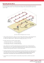
The ProReact EN Analogue Sensor Cable Test Kit can be used to carry out a functional test on a ProReact EN Analogue LHD system. The 
test kit is designed to heat up between 1% and 3% of the sensor cable, simulating a real fi re or overheat condition. A typical test setup 
is shown in Figure 4.

1.   Determine the zone length of the sensor cable that is to be tested. If the zone length is not known, it can be calculated by dividing 

the calibration resistance in kohms (which should be recorded on the label on the reverse of the controller lid) by 0.017. 
For example, if the calibration resistance is 1.50kohms then the zone length is approximately 1.5 / 0.017 = 88m.

2.   Based upon the zone length, select the most suitable heating cable:


1.  Zone length between 50m to 125m 

 select ProMinder Red cable


2.  Zone length between 100m to 350m 

 select ProMinder Blue cable


3.  Zone length between 175m to 500m 

 select ProMinder Brown cable

3.   Locate a suitable section of sensor cable to attach the heating cable to. A minimum of 1% of the sensor cable will need to be 

heated but for the best test results, try and attach the heating cable to approximately 3% of the sensor cable. For example, if the 
zone length is 88m as previously calculated, attach the ProMinder Red cable to 2.6m (3% of 88 metres) section of sensor cable. It is 
acceptable to attach the heating cable to more than 3% of the sensor cable if possible.

4.   The heating cable should be in close proximity to the sensor cable for the heat to transfer eff ectively. It is acceptable for the sensor 

cable and heating cable to touch each other. To further aid in the heat transfer fi x pipe insulation around the heating cable and 
sensor cable to prevent excessive heat loss during the test. 

Not enough heat is generated by the heating cable to raise the 

temperature of the sensor cable suffi  ciently in order to trigger an alarm without the use of the pipe insulation.

5.   The pipe insulation is provided in 450mm lengths so it can be fi xed between support brackets installed at the recommended 

spacing.

Figure 4: Typical ProReact EN Analogue Sensor Cable Test Kit setup

Содержание ProReact EN Analogue

Страница 1: ... www thermocable com Linear Detection Technology Made Simple Page 1 of 8 Revision 1 0 Mar 2020 ProReactENAnalogueCableTestKitInstructions DocumentRef PACC CTK ProReactENAnalogue LinearHeatDetection SensorCableTestingInstructions ...

Страница 2: ...ar 2020 ProReactENAnalogueCableTestKitInstructions DocumentRef PACC CTK Contents ProReact EN Analogue Sensor Cable Test Kit Page 3 Overview Kit Contents Technical Information Operating Instructions Page 6 Troubleshooting Page 8 ...

Страница 3: ...have been made accessible during the system design and installation as per the manufacturer s recommendations A functional test is straightforward to be undertaken and a test kit can be re used where necessary Kit Contents Each ProReact EN Analogue Sensor Cable Test Kit A1900 contains Part Code Product Description Quantity Spare part availability A1904 120V 240Vac to 50Vac Power supply unit 1 3 A1...

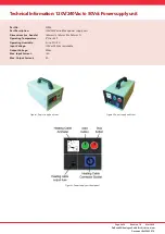
Страница 4: ...chnicalInformation 120V 240Vacto50VdcPowersupplyunit Part No A1904 Part Description 120V 240Vac to 50Vac power supply unit Dimensions inc handle 185mm H x 160mm W x 260mm D Operating Temperature 0 C to 50 C Operating Humidity 0 to 90 RH Input Voltage 120V or 240Vac switchable Output Voltage 50Vac Max Input Current 1 5A Max Output Current 5A Figure 1 Power supply unit rear ...

Страница 5: ...ture 40 C to 40 C Operating Humidity 0 to 99 RH Thermal Power Output Approx 15W m Part code Part Description Heated Length m A1901 ProMinder Red Cable for zone lengths between 50m 125m 3 6 A1902 ProMinder Blue Cable for zone lengths between 100 350m 10 2 A1903 ProMinder Brown Cable for zone lengths between 175m 500m 16 6 each cable includes 5m cold lead with plug on for connecting to power supply ...

Страница 6: ...select ProMinder Brown cable 3 Locate a suitable section of sensor cable to attach the heating cable to A minimum of 1 of the sensor cable will need to be heated but for the best test results try and attach the heating cable to approximately 3 of the sensor cable For example if the zone length is 88m as previously calculated attach the ProMinder Red cable to 2 6m 3 of 88 metres section of sensor c...

Страница 7: ... and instruction manual for guidance If the alarm temperature setting was changed always return the setting to the original value once the test is completed 13 Press the green Start button on the front panel of the power supply unit to start the test The green Start button will light up and the red Stop button light will turn off The power supply unit supplies power to the heating cable for approx...

Страница 8: ...r does not move after the green button is pressed check the cable is attached correctly to the power supply unit Disconnect power to the power supply unit and check the fuse on the front panel see Figure 3 The fuse can be removed by twisting the fuse plug anti clockwise If the power supply unit red Stop button does not light up after connecting the unit to a mains supply Check the fuse on the main...

Отзывы: