
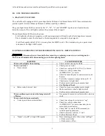

All installations and services must be performed by qualified service personnel.
13
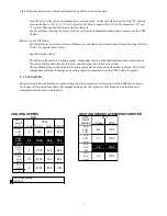
BLOWER Off-
Delay Active?
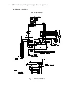
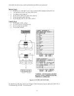
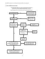
Sequence of Operation
BURNER On
1. A/C Off
2. COOL mode Off
3.BLOWER Off-Delay Started
4. Status LED Off
BLOWER
= LOW
BLOWER = COOL
COOL
Mode On?
Y
Active?
On-Delay
Ended?
Yes
Yes
Yes
Yes
No
No
No
No
DEHUM
Active?
BLOWER = LOW
1. BLOWER Off (No Delay)
2. Status LED Off
1. HEAT mode On
2. BLOWER = HEAT
3. Status LED Flashes
1. COOL mode On
2. Blower On-Delay Started
3. Condenser On
4. Status LED On (continuous)
1. FAN mode On
2. BLOWER = LOW
3. Status LED On (continuous)
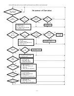
G Active?
Y Active?
LIMIT
Active?
FAN Mode
On?
G
Active?
W Active?
1. HEAT mode On
2. Blower On-Delay Started
3. Burner On
4. Status LED On (continuous)
Yes
Yes
Yes
Yes
Yes
Yes
No
No
No
No
No
No
Yes
No
1.BURNER Off
2. HEAT mode Off
3. BLOWER Off-Delay Started
4. Status LED Off
HEAT
Mode On?
W
Active?
LIMIT
Active?
On-Delay
Ended?
Yes
Yes
Yes
Yes
No
No
No
No
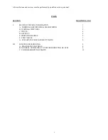
Содержание OL11-105FDBE
Страница 2: ......