


All installations and services must be performed by qualified service personnel.
11
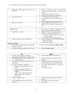
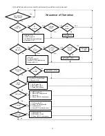
Moisture Check
Connectors are orientated “down” (or as recommended by equipment manufacturer)
Arrange harnesses with “drip loop” under motor
Is condensate drain plugged?
Check for low airflow (too much latent capacity)
Check for undercharged condition
Check and plug leaks in return ducts, cabinet
Comfort Check
Check proper airflow settings
Low static pressure for lowest noise
Set low continuous-fan CFM
T’stat in bad location?
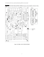
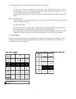
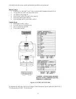
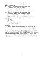
Figure 3: ECM PIN CONNECTORS
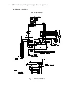
Troubleshooting table above and Figure 2 adapted from GE Industrial Systems publication GED-7161C,
“Troubleshooting GE ECM – Driven Systems”.
Содержание OL11-105FDBE
Страница 2: ......