Thermo Electron 3721 Скачать руководство пользователя страница 10

5

Located on the chart recorder printed circuit board
is an offset potentiometer R3. If for some reason
the recorder output voltage does not match the
temperature as shown in the chart, this
potentiometer can be used to tune it in.

When connecting a chart recorder to the recorder
output connector, it is recommended to use a
shielded cable with the shield grounded at the chart
recorder and to keep the cable short as possible.

INSTRUMENTATION PORT

Located on the rear side of the incubator is an
instrumentation port for the user to insert sensor
wires, external meter leads, etc. into the chamber.
The rubber plug provided must always be used in
this port to insure the uniformity specifications. An
extra plug is supplied for the user's convenience.
Be sure to seal any gaps around the wire(s) going
through the plug.

Содержание 3721

Страница 1: ...cessor Controlled Low Temperature Incubator Model 815 3721 3722 Thermo Electron Corporation Millcreek Road Box 649 Marietta Ohio 45750 USA Phone 740 373 4763 Toll Free 800 848 3080 FAX 740 373 4189 ManualP N3177879 Rev E Dated 1 June 2005 ...

Страница 2: ...N CORPORATION MAKES NO REPRESENTATIONS OR WARRANTIES WITH RESPECT TO THIS MANUAL IN NO EVENT SHALL THERMO BE LIABLEFORANYDAMAGES DIRECTORINCIDENTAL ARISINGOUTOFORRELATEDTO THE USE OF THIS MANUAL For repair information or replacement parts assistance from the manufacturer call Technical Services using our toll free telephone number 888 213 1790 FAX 740 373 4189 ...

Страница 3: ...MENDED PAGES NOTES REVISION STATUS 6 99 B 8 99 19 Update parts list for new kit s C 9 01 Removed dual fans updated parts list 18 20 D E 12 04 6 05 Update for base model FFU2064DW1 manual manufacturelocation 18 20 36100114 34001729 ...

Страница 4: ...formation 2 Performance Data 2 Explanation of Controls 3 Instrumentation Port 5 Installation 6 Operation 7 Servicing 8 Troubleshooting 8 Maintenance 12 Installation and Operation of the RS232 Option 13 Wiring Diagrams 17 Parts Replacement List 19 Warranty 20 ...

Страница 5: ......

Страница 6: ...ndise was carefully packed and thoroughly inspected before leaving our factory Responsibility for safe delivery was assumed by the carrier upon acceptance of the shipment therefore claims for loss or damage sustained in transit must be made upon the carrier by the recipient as follows 1 Visible Loss or Damage Note any external evidence of loss or damage on the freight bill or express receipt and h...

Страница 7: ...ng maintained the compressor operates continuously This constant operation alleviates component failures associated with cycle type operation The circulating fan provides even air distribution throughout the chamber and assures temperature uniformity CATALOG NO 3166745 CAN BE CONVERTED FOR OPERATION ON 200V OR 240V BY CHANGING INPUT CONNECTIONS TO THE AUTOTRANSFORMERS SEE WIRING DIAGRAM ON PAGE 17...

Страница 8: ...rnal audible alarm and to also de activate the external alarm device if one is being used 6 HIGH LOW LIMIT KEY This key is used to view the high or low temperature alarm setpoint The first depression of the key selects the high limit The second depression selects the low limit The respective green indicator lamp will light 7 SET TEMP CAL KEY This key is used to view the operating setpoint temperat...

Страница 9: ... C Recorder Output Millivolts 10 100 0 200 10 300 20 400 30 500 40 600 50 700 In this configuration the light will go off in a high or low temperature alarm condition NOTE WIRING MUST CONFORM TO ALL LOCAL ELECTRICAL CODES 3 RS 232 OUTPUT Optional Kit P N 51200906 This output is used for two way communications between the incubator and a personal computer With the use of communications modem softwa...

Страница 10: ...commended to use a shielded cable with the shield grounded at the chart recorder and to keep the cable short as possible INSTRUMENTATION PORT Located on the rear side of the incubator is an instrumentation port for the user to insert sensor wires external meter leads etc into the chamber The rubber plug provided must always be used in this port to insure the uniformity specifications An extra plug...

Страница 11: ... the user to have it replaced with a properly grounded three prong wall receptacle WARNING DO NOT UNDER ANY CIRCUMSTANCES CUT OR REMOVE THE THIRD GROUND PRONG FROM THE POWER CORD DO NOT USE A TWO PRONG ADAPTER PLUG Determine the total amount of current presently being used by other apparatus connected to the circuit that will be used for this unit It is critical that the added current demand and o...

Страница 12: ... a wide range of temperatures Due to the slight non linearities in the control system it may be necessary to make the display match a calibrated thermometer s reading even though the difference might be only a few tenth s of a degree The CALIBRATE key should be used ONLY to match a stable incubator s actual temperature to the calibrated thermometer Place a calibrated thermometer or the probe of on...

Страница 13: ...Step D and or Remedy 4 Temperature variations at set point poor control Excessive ambient temperature variations see Remedy 10 Compressor Relay failure see Remedy 12 No air circulation in chamber inoperative fan see Remedy 1 RTD Temperature Probe Location see Remedy 5 Ice buildup on evaporator coils see paragraph on Defrosting RTD Temperature probe see Remedy 3 Step D and or Remedy 4 Power Supply ...

Страница 14: ...ll screws that fasten the cover Locate nylon connector J1 on the Limit Alarm PCB Assembly Depress both ears on the plug housing and gently pull out the connector With an Ohmmeter measure the resistance between TB1 4 Orange wire and TB1 6 Red wire The proper heater resistance is 24 ohms If heater resistance is correct then measure between one heater lead RED or ORANGE and incubator ground it must b...

Страница 15: ...ould not be requesting heat as indicated by the Heater On indicator lamp on the front panel It should not be on continuously or even flashing Measure the voltage at U1 Pin 2 with respect to TP2 It should be no less than 4 volts DC Measure the DC voltage across R4 since the incubator is not requesting heat there should be no current flowing through this resistor making the voltage drop equal to zer...

Страница 16: ... Location The Proper RTD location is important The RTD is supported by the stainless steel bracket attached on the rear wall and near the top of the chamber Two tube shaped clips securely support the RTD probe into place The RTD must be inserted fully into its support bracket 6 Constantly Experiencing Low temperature Alarm If the incubator is constantly going into low temperature alarm then most l...

Страница 17: ...he starting relay is overriding the control circuit This may be the result of excessive 90 F ambient temperature adjacent to the compressor excess dirt on the compressor or a relay malfunction Provide additional wall clearance and or circulation around the unit clean compressor or contact Technical Services MAINTENANCE The design of the incubator is such that periodic maintenance is kept to a mini...

Страница 18: ...el and secure with the eight 8 screws The RS232 PCB provides a bi directional communication port that will allow the user to monitor the performance or the change the operating valves of the incubator from a remote computer RS232 Communication will require a communication program such as a modem program installed in your computer which will allow the storage of data within your files The RS232 PCB...

Страница 19: ...e for the Baud Rate desired 3 300 6 600 12 1200 24 2400 48 4800 96 9600 Press the UP or DOWN key until the display reads your selection Press ENTER The baud rate has been entered 2 The display should change to the following Again the number in the display might be different than 0 1 but it will have a decimal point Choose the number appropriate for the Status Update Time Interval desired 0 0 Minut...

Страница 20: ...2 Port as long as the status update time interval is not 0 0 If you start your communication software with the incubator on most likely you will see the error s messages as follows ERR VALUE IS READ ONLY ILLEGAL COMMAND Wait for the Status Update Time duration you selected to complete and the communications will correct itself Besides having the incubator transmit information in one of the three f...

Страница 21: ...ud S Status Update Time Interval The time between data messages sent from the incubator to your computer 0 0 Minutes No report 1 0 1 Minutes 6 seconds 2 0 5 Minutes 30 seconds 3 1 0 Minutes 4 2 0 Minutes 5 5 0 Minutes 6 10 0 Minutes 7 30 0 Minutes 8 60 0 Minutes V EPROM Version Number The incubator software version level D Status Display Type Selection of format that data is sent to your computer ...

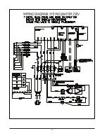
Страница 22: ...17 WIRING DIAGRAMS ...

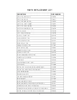
Страница 23: ...18 ...

Страница 24: ...PLUG 230V 3176551 HARNESS 815 BOD 230V 3177652 FUSE KIT 5 AM P 230V 3167219 RS232 COMMUNICATIONS OPTION 3166245 THERM AL CUTOFF SW ITCH 3175264 STOPPER KIT 3167215 DOOR ASSEMBLY 1997 1999 3167221 DOOR GASKET 3174684 M OTOR FAN DUAL REAR M ODEL M FU20F36W 9 3174949 MOTOR FAN REAR M ODEL FFU2064DW 1 3185173 AUTO TRANSFORM ER 3174991 FREEZER FAN M OTOR 3175900 INS TEM P SENSOR BRACKET 316129 BACK HAR...

Страница 25: ...l warranty period The Technical Services Department must give prior approval for return of any components or equipment At Thermo s option all non conforming parts must be returned to Thermo Electron Corporation postage paid and replacement parts are shipped FOB destination THIS WARRANTY IS EXCLUSIVE AND IN LIEU OF ALL OTHER WARRANTIES WHETHER WRITTEN ORAL OR IMPLIED NO WARRANTIES OF MERCHANTABILIT...

Страница 26: ......

Отзывы: