background image


DTH Electric Boilers USE & CARE MANUAL 

(Revision June 2014)

,  Page 

23.


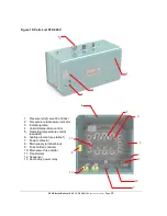
Figure 10: Parts List DTH 600V 


1.  Pressure relief valve 30 or 60psi 
2.  Temperature & pressure indicator 
3.  Indicating lamp 
4.  Hi-limit temperature control 
5.  Operating temperature control 

(aquastat) 

6.  heating element (see table 1) 
7.  Power contactor 
8.  Main supply terminal block 
9.  Fuse holder (controls) 
10. Main power fuse holder 
11. Transformer 
12. Sequencer 
13. Secondary power relay


 3  


10 

11 

12 

  8 

13 

Содержание DTH 102

Страница 1: ...proper installation operation and maintenance of this product It is imperative that all persons who are expected to install operate or adjust this electric boiler should read these instructions carefully to fully understand how to do so Any questions regarding the operation maintenance service or warranty of this electric boiler should be directed to the supplier When all installation steps have b...

Страница 2: ...6KW 14 14 14 4 3 DTH 90 90 375 15 X 6KW 15 15 15 4 3 DTH 96 96 400 16 X 6KW 16 16 16 4 3 Table 2 Electric Ratings for 480 VAC 3 phases Electric Boilers Model P Kw Current Amp Élements 277V Stages Aquastats Lights Power contactors Secondary contactors Sequencers DTH 45 45 54 9 X 5KW 3 3 3 2 3 1 DTH 54 54 65 9 X 6KW 3 3 3 2 3 1 DTH 60 60 72 12 X 5KW 4 4 4 2 4 1 DTH 72 72 87 12 X 6KW 4 4 4 2 4 1 DTH ...

Страница 3: ... 5Kw 6 6 6 3 6 2 DTH 108 108 104 18 x 6 KW 6 6 6 3 6 2 DTH 120 120 115 24 X 5KW 8 8 8 4 8 3 DTH 132 132 127 12 X 5KW 12 X 6KW 8 8 8 4 8 3 DTH 144 144 139 24 X 6KW 8 8 8 4 8 3 Table 4 Connections sizes Boiler overall dimensions Connections sizes Boiler overall dimensions Boiler inlet 2 NPT M Height 33 po Boiler outlet 2 NPT M Depth 46 po Waterworks 1 2 NPT M Width 22 po Safety valve 3 4 NPT F Shipp...

Страница 4: ...DTH Electric Boilers USE CARE MANUAL Revision June 2014 Page 4 Figure 1 Component identification ...

Страница 5: ...on In any case where instructions in this manual differ from local or national codes the local or national codes take precedence 2 2 CORROSIVE ATMOSPHERE The electric boiler should not be located near an air vent containing a corrosive atmosphere or high humidity The limited warranty is void when the failure of the electric boiler is due to a corrosive atmosphere 2 3 SHIPMENT INSPECTION Inspect th...

Страница 6: ... to physical damage for example by moving vehicles area flooding etc All models can be installed on combustible floors and in alcoves Ambient temperature must not exceed 80 F or 27 C 3 3 CLEARANCE Minimum clearances for adequate inspection and servicing are listed in the following table Table 4 Boiler clearance Left side 14 inches Right side 14 in 78to144kW 480 600v 54to96kWx 240v 0in Other models...

Страница 7: ...um allowable pressures and maintain minimum pressure for all normal operating temperatures They also allow air bleeding prevent cavitation at the pump inlet and prevent water from boiling within the system all this is accomplished with minimal addition of new water The increase in boiler water volume resulting from higher temperature is stored in the expansion tank during periods of high operating...

Страница 8: ...perature minus the return boiler water temperature For example a boiler might have a return temperature of 140 F Assuming a constant supply boiler temperature of 180 F the BWTD would be 40 F 180 F 140 F Second example If the boiler water has a return temperature of 120 F and the boiler supply is at 140 F then the temperature drop is 20 F 140 F 120 F The following table suggests temperature drops B...

Страница 9: ...it of 4 feet per second for 2 inch pipe and smaller and a pressure drop limit of 4 feet of water per hundred feet for piping over 2 inches These limitations are imposed either to control the levels of pipe and valve noise erosion and water hammer pressure or for economic reasons Please note that in the smaller pipe sizes this velocity limit permits the use of friction loss rates higher than 4 feet...

Страница 10: ...e valve will power the boiler pump upon opening fully See figure 7 for more details If the heating system is set up to use only a single pump then to minimize flow by gravity heat loss during non draw periods a flow check must be installed 3 7 CONNECTING THE THERMOSTAT The thermostat shall not be connected directly on the boiler Its function is to activate the circulating pump s to bring cold retu...

Страница 11: ... DTH boiler is equipped with an external terminal block facilitating the connection between the two units In Oil Mode The CBE EM dual energy control will start up the oil burner upon receiving a demand signal It will shut off when the temperature in the boiler reaches its target on the Limit Control or when the heat demand has been satisfied In Electric Mode the electric boiler is activated and wi...

Страница 12: ...DTH Electric Boilers USE CARE MANUAL Revision June 2014 Page 12 Figure 2 Wiring diagram DTH 96KW 240V ...

Страница 13: ...DTH Electric Boilers USE CARE MANUAL Revision June 2014 Page 13 Figure 3 Wiring diagram DTH 144KW 480V ...

Страница 14: ...DTH Electric Boilers USE CARE MANUAL Revision June 2014 Page 14 Figure 4 Wiring diagram DTH 144KW 600V ...

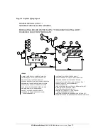
Страница 15: ...W CHECK VALVE REQUIRED ON SYSTEMS WITHOUT MOTORIZED ZONE VALVES CLAPET ANTI GRAVITÉ REQUIS SUR SYSTÈME N AYANT PAS DE ROBINETS MOTORISÉS 14 HOT WATER BASEBOARD PLINTHES CHAUFFAGES 13 MOTORIZED ZONE VALVE ROBINETS MOTORISÉS 10 TEMPERATURE AND PRESSURE GAUGE THERMOMANOMÈTRE 1 MAIN WATER SUPPLY ALIMENTATION D EAU 2 MAINTENANCE VALVE VALVE D ENTRETIEN 3 CHECK VALVE CLAPET ANTI RETOUR 4 PRESSURE REDUCE...

Страница 16: ...MAINTENANCE VALVE VALVE D ENTRTIEN 3 CHECK VALVE CLAPET ANTI RETOUR 4 PRESSURE REDUCER RÉDUCTEUR DE PRESSION 5 EXPANSION TANK RÉSERVOIR DE DILATATION 6 CIRCULATING PUMP POMPE RECIRCULATION 7 PURGE VALVE ROBINET D ÉLIMINATION D AIR 8 DRAIN VALVE VALVE DE DRAINAGE 11 AUTOMATIC AIR VENT PURGEUR D AIR 9 SAFETY VALVE SOUPAPE DE SÛRETÉ 12 SUPPLY HEADER COLLECTEUR D ALIMENTATION 14 RADIANT IN FLOOR PIPIN...

Страница 17: ...ALIMENTATION D EAU 2 MAINTENANCE VALVE VALVE D ENTRETIEN 3 CHECK VALVE CLAPET ANTI GRAVITÉ 4 PRESSURE REDUCER RÉDUCTEUR DE PRESSION 5 EXPANSION TANK RÉSERVOIR DE DILATATION 6 CIRCULATING PUMP POMPE RECIRCULATION 8 DRAIN VALVE VALVE DE DRAINAGE 9 SAFETY VALVE SOUPAPE DE SÛRETÉ 7 PURGE VALVE ROBINET D ÉLIMINATION D AIR 10 TEMPERATURE AND PRESSURE GAUGE THERMOMANOMÈTRE LEGEND 15 INJECTION VALVE SLOW ...

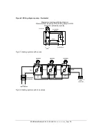
Страница 18: ...diagram pump thermostat Diagramme électrique Wiring diagram Raccordement de pompe DTH Wiring pump for DTH Relais de pompe pump relay T T 1 2 3 4 L2 L1 Pompe Pump jumper Thermostat Relais Relay RA89A 120Vac Fig 8 1 Heating systems with pumps Fig 8 2 Heating systems with zone valves ...

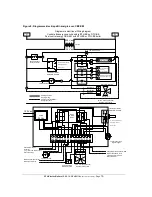
Страница 19: ...ur Wiring by others H H V1 V2 V3 E1 E2 Valve 3 voies optionnelle Optional 3 way valve Contact externe External contact Lumière haut tarif High tarif light Transfo 120 Vac 24 Vac Interrupteur DPDT Switch ON OFF ON Bi energie Dual energy Electrique Electric Mazout Oil DPST Relais Relay Chaudière mazout Oil boiler T T relais de combustion oil boiler burner DPST Relais Relay T6 T5 Relais Pompe Externe...

Страница 20: ... been done Safety and energy conservation are factors to be considered when setting the boiler water temperature using the aquastats The most energy efficient operation will result when the temperature setting of each aquastat is the lowest that satisfies the heating needs Please refer to table 5 for more details Each aquastat controls one stage in the 240V model each electric element has it own a...

Страница 21: ...lish an heating demand from the distribution system 8 The circulator should start 9 The elements should turn on in sequence as the boiler water temperature drops below the aquastat set points This could take many minutes 10 The circulator stays on for as long as there is a demand for heating 11 When the circulator turns off temperature inside the boiler should increase Elements and pilot lights sh...

Страница 22: ...e the cause of the high pressure and have it corrected rapidly Do not plug the outlet of this valve if a dripping condition occurs 5 3 AIR PURGE Twice a yeat Check for proper operation of the automatic air purgers and activate manual air vents to eliminate air present 5 4 ELECTRIC INSPECTION Annually It is recommended to perform a visual inspection of the boiler electric compartment annually durin...

Страница 23: ...Temperature pressure indicator 3 Indicating lamp 4 Hi limit temperature control 5 Operating temperature control aquastat 6 heating element see table 1 7 Power contactor 8 Main supply terminal block 9 Fuse holder controls 10 Main power fuse holder 11 Transformer 12 Sequencer 13 Secondary power relay 3 5 6 7 9 10 11 12 8 2 4 13 9 3 3 ...

Страница 24: ...ons resulting from installation repair maintenance and or usage that are not done in conformity with the manufacturer s installation manual or 2 Defects or malfunctions resulting from installation maintenance or repair that are not done in accordance with regulations in force or 3 Defects or malfunctions resulting from improper installation maintenance or repair done carelessly or resulting from c...

Отзывы: