22
Страница 1: ...ENGLISH ITALIANO AFIP A50 PLUS ISTRUZIONI D INSTALLAZIONE INSTALLATION INSTRUCTIONS Unità interna Indoor unit ...
Страница 2: ...rcato in quanto conforme alle Direttive Bassa Tensione n 2014 35 UE Standard EN60335 2 40 2003 incl Corr 2006 A11 2004 A12 2005 A13 2012 A1 2006 A2 2009 with EN 60335 1 2002 A11 2004 A1 2004 A12 2006 A2 2006 A13 2008 A14 2010 A15 2011 Compatibilità Elettromagnetica n 2014 30 UE 92 31 CEE e 93 68 CEE Standard EN55014 1 2006 A1 2009 A2 2011 EN 55014 2 1997 A1 2001 A2 2008 EN 61000 3 2 2006 A1 2009 A...
Страница 3: ...to con i tubi refrigeranti il compressore o le parti mobili del ventilatore Nel collegare l alimentazione e le linee di controllo non usare cavi a più conduttori Usare cavi separati per ciascun tipo di linea Durante il trasporto Fare attenzione nel sollevare e nello spostare le unità interna ed esterna È consigliabile farsi aiutare da qualcuno e piegare le ginocchia quando si solleva per evitare s...
Страница 4: ...nte ventilate Fissare l unità alla base di appoggio per evitare vibrazioni continua a pag 8 LIMITI SU LUNGHEZZA TUBI DI COLLEGAMENTO E DISLIVELLO V ISTRUZIONI DI INSTALLAZIONE UNITA ESTERNA CONTATTO IN INGRESSO ON OFF J11 verde Lo stato di questo ingresso provoca le seguenti modalità di funzionamento del sistema del sistema l Contatto APERTO sistema non in funzione sempre OFF I comandi provenienti...
Страница 5: ...Directives Low voltage no 2014 35 UE Standard EN60335 2 40 2003 incl Corr 2006 A11 2004 A12 2005 A13 2012 A1 2006 A2 2009 con EN 60335 1 2002 A11 2004 A1 2004 A12 2006 A2 2006 A13 2008 A14 2010 A15 2011 Electromagnetic compatibility no 2014 30 UE 92 31 EEC and 93 68 EEC Standard EN55014 1 2006 A1 2009 A2 2011 EN 55014 2 1997 A1 2001 A2 2008 EN 61000 3 2 2006 A1 2009 A2 2009 EN 61000 3 3 2008 RoHS2...
Страница 6: ...w wiring to touch the refrigerant tubing compressor or any moving parts of the fan Do not use multi core cable when wiring the power supply and control lines Use separate cables for each type of line When transporting Be careful when picking up and moving the indoor and outdoor units Get a partner to help and bend your knees when lifting to reduce strain on your back Sharp edges or thin aluminium ...
Страница 7: ...down the unit reducing vibration and noise go on page 8 EG TUBING LENGTH AND ELEVATION DIFFERENCE LIMITS SEE INSTALLATION INSTRUCTIONS OF OUTDOOR UNIT INPUT CONTACT ON OFF J11 green The status of this input affects system operation according to the following Contact OPEN system does not operate always OFF inputs from wireless remote controller are not processed Contact CLOSED system operates in th...
Страница 8: ...lic and electrical connections b CAUTION The spacers with the grooves must be fitted in the two top holes the others in the two bottom holes EN I L unità può essere collegata in cinque direzioni laterale posteriore destro e sinistro lato destro lato sinistro verso il basso lato destro The unit can be connected to five directions right rear left rear right side left side and right downward EN I B E...
Страница 9: ... made on the wall check the horizontal position with the level OPTIONAL HOLES EN I Predisporre il fissaggio dell unità Predispose the fixing of the unit EN I Collegamento tubi laterali Tagliare l angolo della copertura Tubing connections on right or left side Cut a corner of the frame H NO NO YES Usando le viti fissare l unità al muro Make sure the panel is flush against the wall Any space between...
Страница 10: ...e EN I Per rimontare il pannello frontale inserirlo nella parte bassa dell unità allinearlo sui punti di bloccaggio applicare una leggera pressione sui punti indicati To fix the front panel again insert it in the lower side of the unit and align it with the blocking points Then push lightly on the shown marks EN I L unità interna può essere installata senza rimuovere il pannello frontale Se necess...
Страница 11: ... quindi togliere il tappo in gomma sull altro lato Rimontare invertendo le posizioni usare un cacciavite per riposizionare correttamente il tappo How to reverse the drain hose position Remove the drain hose by turning it counterclockwise then remove the rubber plug on the other side of the unit Replace them inverting their position use a screwdriver to place the plug correctly I EN O Stendere un c...
Страница 12: ...bes connecting the units from the outside then bend them upwards I EN USCITA TUBAZIONI LATO SINISTRO POSTERIORE Appendere l unità ed avvitare parzialmente le viti Inserire le tubazioni di collegamento dall esterno quindi piegarle verso destra rimuovere la parte inferiore amovibile della struttura Nel caso in cui i tubi non avessero la lunghezza sufficiente per realizzare il collegamento frontale i...
Страница 13: ...wiring with clamp provided See wiring diagrams Loose wiring may cause the terminal to overheat or result in unit malfunction A fire hazard may also exist Therefore be sure all wiring is tightly connected T EN I WARNING AVVERTIMENTO U Convogliare la condensa verso l esterno assicurando una buona pendenza Sifonare se necessario Install the condensate drain to the outside with a positive slope form a...
Страница 14: ...ide of indoor unit I EN PREDISPOSIZIONE STANDARD Collegamento frontale parte destra unità interna Nel caso in cui i tubi non avessero la lunghezza sufficiente per realizzare il collegamento frontale impiegare i tubi ed isolanti a corredo STANDARD PREARRANGEMENT Front connection right side of indoor unit In case the tubes should not be long enough for the front connection use the supplied tubes and...
Страница 15: ...dell unità esterna Il cavo non deve essere più leggero del tipo H07RN F secondo CEI 20 19 CENELEC HD22 Assicurarsi che la lunghezza dei conduttori fra il punto di fissaggio del cavo ed i morsetti sia tale che i conduttori attivi si tendano prima del conduttore di messa a terra Connecting wire B SHIELDED Bipolar electric shielded wire size and length of the suggested electric wire are showed on tab...
Страница 16: ... Behind a curtain or other places where it is covered More than 8 m away from the air conditioner In the path of the air conditioner s airstream Where it may become extremely hot or cold Where it may be subject to electrical or magnetic noise Where there is an obstacle between the remote control unit and the air conditioner EN I POSIZIONE A PARETE Momentaneamente sistemare il telecomando nella pos...
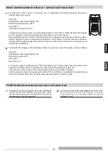
Страница 17: ...to set the remote control as follows Filter ON Night Mode High Power Mode OFF Operation mode AUTO Flap AUTO Set point 10 C At this point press contemporary the FAN and IFEEL keys of the remote control for more than 5 seconds and release them by pointing the remote control towards the indoor unit If the setting is correct you will hear an acoustic signal as confirmation 4 beep After the acoustic si...
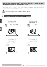
Страница 18: ...T CIRCUIT ADDRESS INSTALLATION Verificare che il microinterruttore SW1 PCB sia impostato come in figura Check that the setting of switch SW1 PCB corresponds to the figure EN I IMPOSTAZIONE INDIRIZZI TRAMITE I MICROINTERRUTTORI FINO A 4 UNITA INTERNE ADDRESS SETTING THROUGH DIP SWITCHES UP TO 4 INDOOR UNITS Accertarsi che la corrente elettrica sia disinserita Disconnect the power UNITÀ INTERNA A UN...
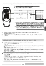
Страница 19: ...Ù Ù Ï ÎÙÚ ÙÔ ÙËÏÂ ÂÈÚÈÛÙËÚ Ô FAN Î È I FEEL Î È Í Ó Ê ÛÙÂ Ù ÛÙÚ ÊÔÓÙ ÙÔ ÙËÏÂ ÂÈÚÈÛÙ ÚÈÔ ÚÔ ÙËÓ ÂÛˆÙÂÚÈÎ ÌÔÓ Ó Â Ó È ÛˆÛÙ ÔÈ Ú ıÌ ÛÂÈ Ë ÂÛˆÙÂÚÈÎ ÌÔÓ ÂÎ Ì ÂÈ Ó Ë ËÙÈÎfi Û Ì Â È Â ˆÛË 4 beep Î È Ú ÂÈ Ó ÏÂÈÙÔ ÚÁÂ ÌÂ ÙËÓ Î ÈÓÔ ÚÈ Ú ıÌÈÛË I EG F D E P GR IMPOSTAZIONE INDIRIZZI TRAMITE TELECOMANDO FINO A 8 UNITA INTERNE ADDRESS SETTING THROUGH REMOTE CONTROLLER UP TO 8 INDOOR UNITS Indoor unit 1 11 C Indo...
Страница 20: ...BINAMENTO TRA TELECOMANDO E UNITA INTERNA MATCH BETWEEN REMOTE CONTROLLER AND INDOOR UNIT l Togliere l alimentazione dell unità interna l Togliere le batterie dal telecomando l Impostare i microinterruttori v tabella l Inserire le batterie nel telecomando l Alimentare l unità interna A questo punto il sistema si riavvia con i nuovi indirizzi l Disconnect the power of indoor unit l Remove the batte...
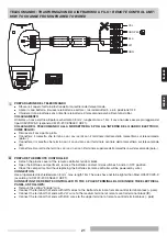
Страница 21: ...avo viola con il terminale centrale della morsettiera sul telecomando IR l Connettere il morsetto che termina con i cavi neri con il terminale superiore della morsettiera sul telecomando polo PREPARE THE REMOTE CONTROLLER l Detach the plastic cover of the remote controller terminal block l Open the batteries compartment remove the batteries and set microswitches 5 and 6 in OFF position l Close the...
Страница 22: ...22 ...
Страница 23: ...23 ...
Страница 24: ...ento di tutta la sua produzione le caratteristiche estetiche e dimensionali i dati tecnici gli equipaggiamenti e gli accessori possono essere soggetti a variazione The manufacturer strives to continuously improve all products Appearance dimensions technical specifications standard equipment and accessories are therefore liable to modification without notice ...