ENGLISH
ITALIANO
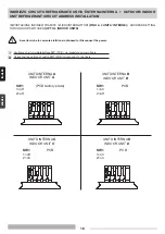
ALL’UNITÀ ESTERNA
TO OUTDOOR UNIT
UNITÀ INTERNA -
INDOOR UNIT
COLLEGAMENTI ELETTRICI DEL SISTEMA
•
SYSTEM WIRING DIAGRAM
LUNGHEZZA, SEZIONE CAVI E FUSIBILI RITARDATI •
LENGTH, SIZE WIRES AND DELAYED FUSE
V. ISTRUZIONI DI INSTALLAZIONE UNITA’ ESTERNA
SEE INSTALLATION INSTRUCTIONS OF OUTDOOR UNIT
I
EN
I
EN
Cavo di collegamento B (SCHERMATO):
Cavo elettrico bipolare schermato; la sezione e la lunghezza del cavo elettrico consigliato sono indicate in
tabella dati elettrici dell’unità esterna. Il cavo non deve essere più leggero del tipo H05VVC4V5-K (secondo
CEI 20-20 CENELEC HD21).
Cavo di collegamento C (con conduttore di terra):
Cavo elettrico multipolare; la sezione e la lunghezza del cavo elettrico consigliato sono indicate in tabella dati
elettrici dell’unità esterna. Il cavo non deve essere più leggero del tipo H07RN-F (secondo CEI 20-19 CENELEC
HD22). Assicurarsi che la lunghezza dei conduttori fra il punto di fissaggio del cavo ed i morsetti sia tale che i
conduttori attivi si tendano prima del conduttore di messa a terra.
Connecting wire B (SHIELDED):
Bipolar electric shielded wire; size and length of the suggested electric wire are showed on table “electrical
data” of outdoor unit. The wires have not to be lighter than Mod. H05VVC4V5-K (according to CEI 20-20
CENELEC HD21).
Connecting wire C (with ground conductor):
Multipolar electric wire; size and length of the suggested electric wire are showed on table “electrical data” of
outdoor unit. The wires have not to be lighter than Mod. H07RN-F (according to CEI 20-19 CENELEC HD22).
Make sure the length of the conductors between the fixing point and the terminals allows the straining of the
conductors L, N before that of the grounding.
UNITÀ INTERNA
-
INDOOR UNIT
15


