33
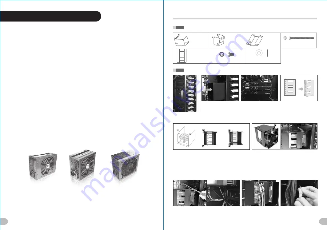
Move the HDD iCage
up 4 bay drives.
Content on this sheet is additional information for page 21 to page 26
of Element V NVIDIA Edition's User's Manual
Put the Fan Duct 1 into the empty
5.25” drive bays.
(Do not secure the Fan Duct 1
onto chassis yet)
Install the graphic cards.
Fold the Mylar along dotted line A
, dotted line B and dotted line C
as shown above.
A
B
Stick the Mylar inside of Fan Duct 2 as shown.
- For 9.6” graphic cards:
Please align the dotted line A along the left edge of the cut-out hole
on Fan Duct 2. (Please note the three cut-out holes on the Mylar are
further away from the left edge of the cut-out on Fan Duct 2)
- For 10.6” graphic cards:
Please align the dotted line B along the left edge of the cut-out hole
on Fan Duct 2. (Please note the three cut-out holes on the Mylar are
closer to the left edge of the cut-out on Fan Duct 2)
Secure the 120 x 38 mm fan on Fan Duct 2.
(Please make sure the airflow of the fan is towards the
Fan Duct 2. The fan has arrow on the side of the casing
indicating the direction of airflow).
Place the Fan Duct 2 over the graphic cards as shown.
Make sure the three cut-out holes on the Mylar are aligned
with the PCI-E power connectors on the graphic cards.
Also make sure the Fan Duct 1 covers the 120 x 38 mm fan
firmly.
Secure Fan Duct 1 and Fan Duct 2 to the motherboard plate
with screws. (Total of 4 screws)
Connect the required PCI-E
power connectors from the power
supply to graphic cards.
Either connect the 3-pin wire of
the 120 x 38
mm fan to the
motherboard’s fan connector or
attach the 3-4
pin wire and
connect to PSU directly.
Part List
Fan Duct 1
x 1 pcs
Fan Duct 2
x 1 pcs
Fan Duct 3
x 1 pcs
6#32 Screw
x 4 pcs
(for 120 x 38 mm fan)
Mylar
x 1 pcs
6#32 Screw
x 4 pcs
Washer
x 4 pcs
(for 120 x 38 mm fan, Quad SLI only)
Dotted line A
Dotted line B
3-WAY SLI INSTALLATION
(Before)
(After)
Dotted line C
Cut-out holes on Mylar.(Further
away from the left edge of
cut-out hole on Fan Duct 2)
Cut-out holes on Mylar.
(Closer to the left edge of
cut-out hole on Fan Duct 2)
(For 9.6” graphic cards)
(For 10.6” graphic cards)
34
The Thermaltake Power Supply series specification meets latest Intel &
AMD dual & Quad core processors and NVIDIA & AMD high performance
graphic cards; it offers plenty of functions, which mainly include:
1. Automatic Fan Speed Control: All power supply can detect the inside
heat and automatically adjust the fan speed to provide adequate airflow.
2. Ultra Silent: Ball bearing fans with high reliability 140mm or 120mm
cooling fan and super low acoustic noise under all load condition.
3. Modularized Cable Management: To eliminate clutter and improve
airflow inside the case.
4. Dedicated Graphic Card Power: reduce the loading on current PSU and
no need to upgrade current PSU while running multi graphic cards mode.
The functions can assure all Thermaltake Power Supply meets the balance
in noise control and heat exhausted. All power supply provides complete
protection function as follow:
1. Over power protection.
2. Short circuit protection on all output.
3. Over voltage protection / Under voltage protection.
4. Over current protection.
5. Over temperature protection.
Besides, Thermaltake enables the quality assurance of all power supply:
100% Hi-POT and ATE Function Test, 100% Burn-In and AC Input cycled
on/off under high temperature condition. Furthermore, it has been approved
by
UL, CUL, TUV, CB, FCC, CE, and BSMI.
There are three main products line of Thermaltake PSU
which divided into Toughpower, Purepower (include
Purepower RX) and TR2 (include TR2 RX) series.
Please refer to
http://www.thermaltake.com/product/Power/power_index.asp
5.0 Toughpower / Purepower /
TR2 power supply series (optional)


