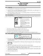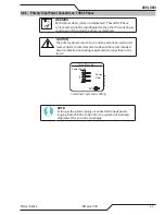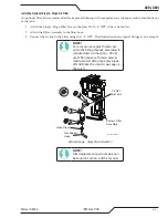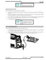
A40i, A60i
Manual 0-5466
OPERATION
4-5
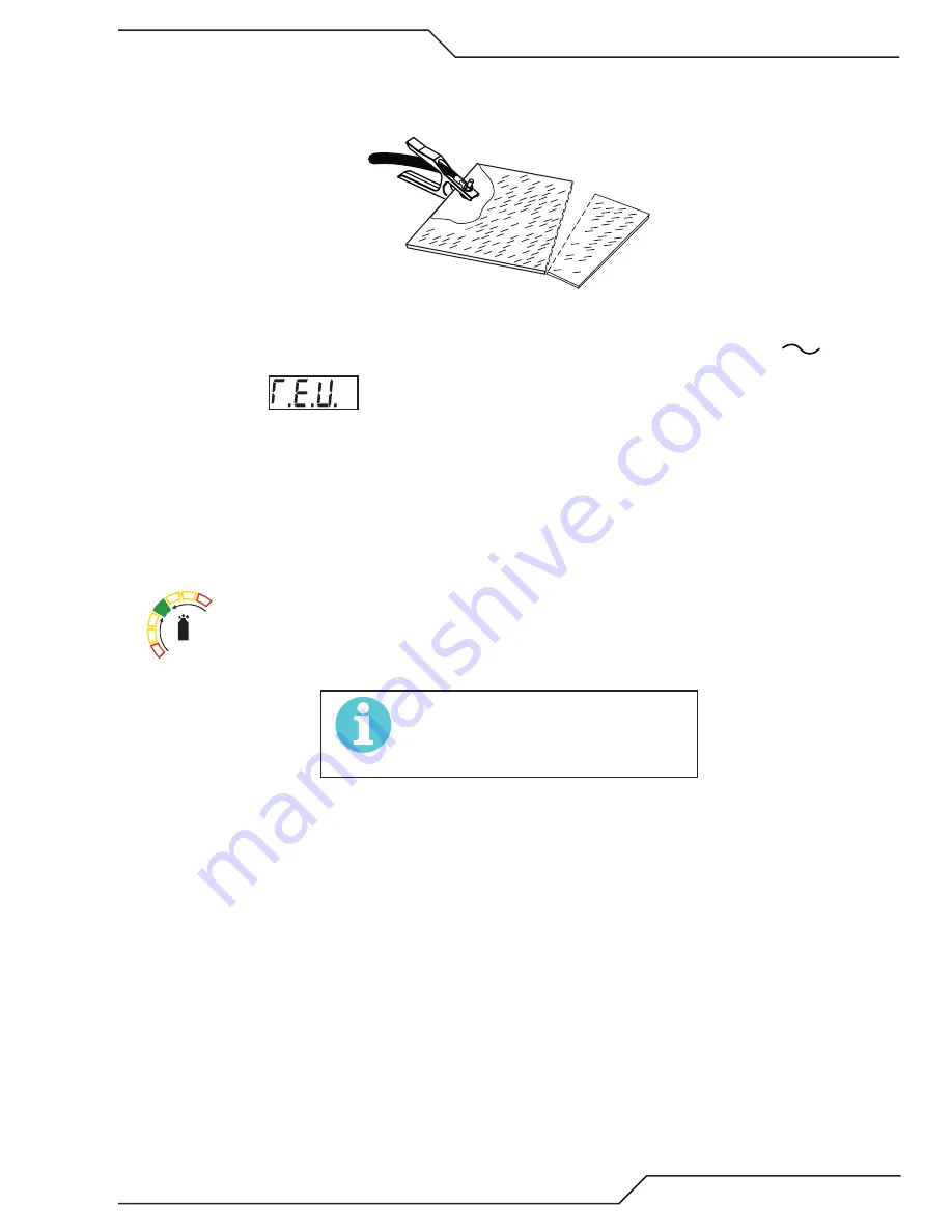
Connect Work Cable
Clamp the work cable to the workpiece or cutting table. The area must be free from oil, paint and rust. Connect only
to the main part of the workpiece; do not connect to the part to be cut off.
Art # A-04509
Power ON
Place the Power Supply ON / OFF switch to the ON (right) position. AC indicator
turns ON.
The Control Board performs several tests to determine the system is ready to operate. During the self-tests the digital
display first shows
(revision) followed by the firmware revision number which includes decimals. 1.1.0
is an example of a production released code revision that may be displayed.
Next displayed is the “checksum” a combination of letters and numbers that are unique to the firmware revision. These
are used by service personal to determine if the firmware has been corrupted.
If there are no issues detected the output current setting will be displayed with the letter "A" to the right, showing the
output current setting. Should a problem be detected the fault code in the format Exxx will display and the “A” will not
be illuminated. Refer to Section 5.04 for fault code explanations.
Gas indicator turns ON if there is sufficient gas pressure for power supply operation and the cooling fan
turns ON. (90 - 125 PSI / 6.2 - 8.6 bar)
NOTE!
Minimum pressure for power supply
operation is lower than minimum for
torch operation.
The cooling fan will turn ON as soon as the unit is turned ON. After a short amount of time the fan
switches to low speed. The fan will return to high speed as soon as the torch switch (Start Signal) is ac-
tivated or if the unit is turned OFF, then turned ON again. If an over temperature condition occurs, the
fan will continue to run at high speed while the condition exists and for a five (5) minute period once
the condition is cleared.
Содержание A40i
Страница 6: ...This Page Intentionally Blank...
Страница 8: ...This Page Intentionally Blank...
Страница 12: ...TABLE OF CONTENTS This Page Intentionally Blank...
Страница 16: ...A40i A60i WARRANTY INFORMATION Manual 0 5466 W 2 This Page Intentionally Blank...
Страница 24: ...A40i A60i INTRODUCTION Manual 0 5466 2T 4 This Page Intentionally Blank...
Страница 32: ...A40i A60i INSTALLATION Manual 0 5466 3 8 This Page Intentionally Blank...
Страница 34: ...A40i A60i INSTALLATION Manual 0 5466 3T 2 This Page Intentionally Blank...
Страница 80: ...A40i A60i OPERATION Manual 0 5466 4T 36 This Page Intentionally Blank...
Страница 95: ...A40i A60i Manual 0 5466 PARTS LIST 6 3 This Page Intentionally Blank...
Страница 99: ...A40i A60i Manual 0 5466 PARTS LIST 6 7 A 07994_AB 1 4 2 3 5 6 7 8 9 10 12 11 10 13...
Страница 110: ...A40i A60i APPENDIX Manual 0 5466 A 10 APPENDIX 8 SYSTEM SCHEMATIC 400V 3PHASE CE Art A 13478...
Страница 111: ...A40i A60i Manual 0 5466 APPENDIX A 11 Art A 13478...
Страница 112: ...A40i A60i APPENDIX Manual 0 5466 A 12 APPENDIX 9 SYSTEM SCHEMATIC 208 480V 3PHASE Art A 13479...
Страница 113: ...A40i A60i Manual 0 5466 APPENDIX A 13 Art A 13479...
Страница 115: ...This Page Intentionally Blank...

