


38
Step 7 – Establish Coolant Flow
Establish flow through the chiller.
Note: The compressor will not start as long as the flow switch is
open. A positive flow must be established through the evaporator
before the compressor can operate.
Set water flow using a discharge throttling valve or
flow control valve (by others). The valve should be
the same size as the To Process connection of the
chiller. Standard chillers are designed for
approximately 2.4 gpm/ton of nominal capacity. A
significant increase in flow beyond this in a standard
chiller may result in excessive pressure loss and
negatively impact chiller efficiency and in extreme
cases may cause premature wear or damage of
internal components.
Step 8 – Initial Unit Operation
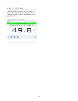
Enter the desired leaving fuid temperature on the
chiller HMI. Unless otherwise specified, the chiller is
factory set to deliver coolant at 50°F. Adjust to the
desired operating temperature. The chiller should
now be controlling to the selected temperature.
Please note that if there is insufficient load the
compressor may cycle on and off causing swings in
temperature.
WARNING: Under no circumstance should the High
Refrigerant Pressure or the Low Compressor Pressure
switch be deactivated. Failure to heed this warning
can cause serious compressor damage, severe
personal injury or death.
Operate the system for approximately 30 minutes.
Check the liquid line sight glass. The refrigerant flow
past the sight glass should be clear. Bubbles in the
refrigerant indicate either low refrigerant charge or
excessive pressure drop in the liquid line. A shortage
of refrigerant is indicated if operating pressures are
low and subcooling is low. Normal subcooling
ranges are from 10°F to 20°F. If subcooling is not
within this range, check the superheat and adjust if
required. The superheat should be approximately
10°F. If the operating pressures, sight glass,
superheat, and subcooling readings indicate a
refrigerant shortage, charge refrigerant as required.
With the unit running, add refrigerant using industry
best practices until operating conditions become
normal.
CAUTION: A clear sight glass alone does not mean
that the system is properly charged. Also check system
superheat, subcooling, and unit operating pressures. If
both suction and discharge pressures are low but
subcooling is normal, a problem other than refrigerant
shortage exists. Do not add refrigerant, as this may
result in overcharging the circuit.
Once proper flow and temperature are achieved,
press the Stop button. The unit is now ready to be
placed into service.
Preventive Maintenance
Once your chiller is in service, follow the
maintenance procedures as closely as possible.
Specific site conditions may require repeating certain
tasks more frequently. The importance of a properly
established preventive maintenance program cannot
be overemphasized. Taking the time to follow these
simple procedures will result in substantially reduced
downtime, reduced repair costs, and an extended
useful lifetime for the chiller. Any monetary costs of
implementing these procedures will usually more
than pay for itself.
To make this as simple as possible, prepare a
checklist with the recommended service operations
and record the date and time when performed. At
the end of this manual, you will find a checklist for
this purpose. Please notice that there are locations
for voltage readings, amperages, etc. for monitoring
over time. With this information, maintenance
personnel may be able to correct a potential
problem before it causes any downtime. For best
results, take these readings with a full heat load from
process, preferably with similar operating conditions
each time. The following is a list of suggested
periodic maintenance.
Once a Week
1.
Check to make sure that the To Process
temperature is reasonably close to the Set Point
temperature. If the temperature stays more than
5°F away from the set point, there may be a
problem with the chiller. If this is the case, refer
to the Troubleshooting Chart or contact our
Customer Service Department.


