4
Each condenser has a two-way condenser water-
regulating valve. The condenser water-regulating
valve controls the amount of water allowed to pass
through the condenser in order to maintain proper
refrigeration pressures in the circuit.
To prevent damage to the condenser and/or water-
regulating valve, the water pressure should not
exceed 150 psig.
Water Pressure Gauges
Install pressure gauges in the inlet and outlet of both
the condenser and evaporator chilled water piping
to provide the ability to read the pressure drop
across the chiller and aid in preventive maintenance
and troubleshooting.
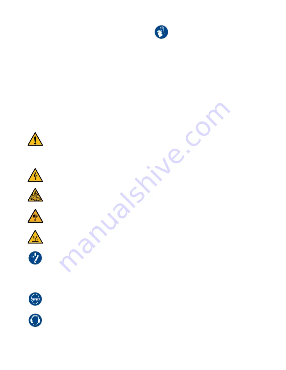
WARNING: Vent all refrigerant relief valves in accordance
to ANSI/ASHRAE Standard 15, Safety Code for Mechanical
Refrigeration. Locate this equipment in a well-ventilated
area. Inhalation of refrigerant can be hazardous to your
health and the accumulation of refrigerant within an
enclosed space can displace oxygen and cause suffocation.
WARNING: This equipment contains hazardous voltages
that can cause severe injury or death.
WARNING: This equipment contains refrigerant under
pressure. Accidental release of refrigerant under pressure
can cause personal injury and or property damage.
WARNING: This equipment may contain fan blades or
other sharp edges. Make sure all fan guards and other
protective shields are securely in place.
WARNING: The exposed surfaces of motors, refrigerant
piping, and other fluid circuit components can be very hot
and can cause burns if touched with unprotected hands.
CAUTION: Disconnect and lock out incoming power before
installing, servicing, or maintaining the equipment.
Connecting power to the main terminal block energizes
the entire electric circuitry of the unit. A power supply
provides 24 VDC control power. Shut off the electric power
at the main disconnect before opening access panels for
repair or maintenance.
CAUTION: Wear eye protection when installing,
maintaining, or repairing the equipment to protect against
any sparks, debris, or fluid leaks.
CAUTION: The equipment will exceed 70 dBA sound
pressure at 1 meter distance and 1 meter elevation when
operating. Wear ear protection as required for personal
comfort when operating or working in close proximity to
the chiller.
CAUTION: Wear protective gloves when installing,
maintaining, or repairing the equipment to protect against
any sparks, debris, or fluid leaks.
System Temperature Sensor
This section only applies to installations where
multiple chillers are in a common system where one
chiller is the primary chiller with the other chillers
serving as secondary chillers. In those situations, a
field-installed fluid-temperature sensor is required in
the common process fluid supply and return piping.
Install the sensor downstream of all individual chilled
water supply streams. Position the temperature
sensor to read the mixed supply temperature. The
supply temperature sensor is normally the control
sensor for the chiller system set point and
determines the loading/unloading of the
compressors of the system.
The temperature sensor comes from the factory with
a ½” NPT male fitting thermowell for direct
mounting in the field piping. Mount the temperature
sensor in a minimum pipe size of 3”. Wire the
temperature sensor to the designated primary chiller
electrical enclosure and land at the appropriate
terminal blocks within the enclosure. See the chiller
electrical schematic for further details.
Chiller Flow Sensor
This section only applies to installations when the
flow sensor option is present. In those situations, a
field-installed chiller flow sensor is required. Mount
the flow sensor in the process fluid supply piping in
an area of pipe with a minimum of 10 pipe diameters
of straight run after any valves or pipefittings. This
ensures the stream of fluid is solid and stable for
accurate flow measurement.
The flow sensor comes from the factory with a ½”
NPT compression fitting for direct mounting in the
field piping. Mount the flow sensor in a minimum
pipe size of 2”. Insert the stem of the sensor into the
compression fitting so the tip of the sensor is at the
approximate center of the pipe. The sensor requires
five pipe diameters of straight run piping on both
sides of the sensor. Wire the flow sensor to the
chiller electrical enclosure and land at the
appropriate terminal blocks with the enclosure. See
the chiller electrical schematic for further details.


