background image


26 


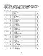
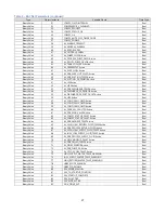
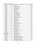
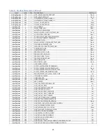
Table 8 – Modbus Parameters (continued) 

Types 

Index 

Size  Variable Name 

Data Type 

InputRegister 146 1 

NQV_EV2_50_AC_INPUT_CURRENT_FOLDBACK_STATUS Int 

InputRegister 147 1 

NQV_EV2_59_POWERUP_STATUS Int 

InputRegister 148 2 

NQV_EV2_POWER_MODULE_TEMP 

Real 

InputRegister 150 2 

NQV_EV2_DLT 

Real 

InputRegister 152 1 

NQV_EV2_78_1ST_FAULT_OCCURRED Int 

InputRegister 153 1 

NQV_EV2_79_1ST_FAULT_OCCURRED Int 

InputRegister 154 1 

COMP1_ANTI_CYCLE_TIME Int 

InputRegister 155 1 

COMP2_ANTI_CYCLE_TIME Int 

InputRegister 160 2 

PUMP_PRESSURE_HMI 

Real 

InputRegister 162 2 

PROCESS_PUMP_PID_PERCENT Real 

InputRegister 180 2 

MOD_VALVE_CTRL_TEMP_HMI Real 

InputRegister 182 2 

MOD_VALVE_PERCENT Real 

InputRegister 190 2 

STAGE1_CUT_IN_TEMP_HMI Real 

InputRegister 192 2 

STAGE1_CUT_OUT_TEMP_HMI 

Real 

InputRegister 194 2 

STAGE2_CUT_IN_TEMP_HMI Real 

InputRegister 196 2 

STAGE2_CUT_OUT_TEMP_HMI 

Real 

InputRegister 202 1 

STAGED_COMPRESSORS_RUNNING Int 

InputRegister 203 1 

STAGED_COMPRESSORS_REQUESTED Int 

InputRegister 204 1 

STAGE_MINUTES_UNTIL_NEXT_STAGE 

Int 

InputRegister 206 1 

RETRANSMIT_PERCENT Int 

InputRegister 226 1 

CHILLER_STATUS 

UInt 

InputRegister 231 2 

EVAP_IN_FLUID_HMI 

Real 


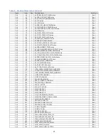
Table 9 – BACNet Parameters 

Type 

Object Instance 

Variable Name 

Data Type 

BinaryValue 1 

HMI_START 

Bool 

BinaryValue 2 

SYSTEM_RUNNING 

Bool 

BinaryValue 3 

HMI_STOP 

Bool 

BinaryValue 4 

SYSTEM_STOPPING 

Bool 

BinaryValue 5 

COMPRESSORS_RUNNING 

Bool 

BinaryValue 6 

PHASE_OK 

Bool 

BinaryValue 7 

EVAP_FLOW_SWITCH_OK 

Bool 

BinaryValue 8 

LPS_OK 

Bool 

BinaryValue 9 

LLPS_OK 

Bool 

BinaryValue 10 

RFRG_HIGH_PRESSURE_OK 

Bool 

BinaryValue 11 

COND_FAN1_EXISTS 

Bool 

BinaryValue 12 

COND_FAN1_OVLD_OK 

Bool 

BinaryValue 13 

ENABLE_FAN_FS1 

Bool 

BinaryValue 14 

COND_FAN2_EXISTS 

Bool 

BinaryValue 15 

COND_FAN2_OVLD_OK 

Bool 

BinaryValue 16 

ENABLE_FAN_FS2 

Bool 

BinaryValue 17 

COND_FAN3_EXISTS 

Bool 

BinaryValue 18 

COND_FAN3_OVLD_OK 

Bool 

BinaryValue 19 

ENABLE_FAN_FS3 

Bool 

BinaryValue 20 

PULSE_2SEC 

Bool 

BinaryValue 21 

SYSTEM_NOT_RUNNING 

Bool 

BinaryValue 22 

COMP1_EXISTS 

Bool 

BinaryValue 23 

COMP1_OVLD_INTERNAL 

Bool 

BinaryValue 24 

COMPRESSOR_1_DISABLED 

Bool 

BinaryValue 25 

COMP1_REQUEST 

Bool 

BinaryValue 26 

COMP1_STATUS_OK 

Bool 

BinaryValue 27 

COMP1_OK 

Bool 

BinaryValue 28 

COMP1_ANTICYCLE_TIMER_DONE 

Bool 

BinaryValue 29 

COMP1_ENABLE 

Bool 

BinaryValue 30 

COMP2_EXISTS 

Bool 


Содержание Accuchiller NQ Series

Страница 1: ......

Страница 2: ......

Страница 3: ...Length 5 Table 1 Equivalent Lengths of Elbows 6 Liquid Line Sizing 6 Table 2 Liquid Line Sizes for R410A 7 Discharge Hot Gas Line Sizing 9 Figure 6 Vertical Riser Traps 9 Figure 7 Double Discharge Ris...

Страница 4: ...Digital Inputs Screen 18 Inputs Outputs Analog Outputs Screen 18 Inputs Outputs Digital Outputs Screen 18 Menu 1 User Setup 18 User Setup Menu Screen 1 18 User Setup Menu Screen 2 18 User Setup Menu...

Страница 5: ...Solutions 32 Step 3 Check Condenser 33 Integral Air Cooled Condenser Check 33 Water Cooled Condenser Check 33 Remote Air Cooled Condenser Check 33 Step 4 Check Refrigerant Valves 33 Step 5 Verify Free...

Страница 6: ...Page Intentionally Blank...

Страница 7: ...at transfer purposes This chemical is sealed and tested in a pressurized system containing ASME coded vessels however a system failure will release it Refrigerant gas can cause toxic fumes if exposed...

Страница 8: ...t against any sparks debris or fluid leaks CAUTION The equipment will exceed 70 dBA sound pressure at 1 meter distance and 1 meter elevation when operating Wear ear protection as required for personal...

Страница 9: ...hoses quick disconnect fittings and manifolds wherever possible as they offer high resistance to water flow When manifolds are required install them as close to the use point as possible Provide flow...

Страница 10: ...can be significantly warmer than surrounding areas Locate the condenser where fan noise and vibration transmission into nearby workspaces is unlikely Install the condenser on a firm level surface Avo...

Страница 11: ...igure 5 The configuration and its associated elevation along with the total distance between the chiller and the condenser are important factors in determining the liquid line and discharge line sizes...

Страница 12: ...0 4 1 10 0 3 2 5 2 3 7 5 5 0 12 0 4 0 6 4 3 9 0 5 9 15 0 4 7 7 3 4 10 0 6 7 17 0 5 2 8 5 Liquid Line Sizing To keep the system refrigerant charge at a minimum use the smallest acceptable line size pos...

Страница 13: ...50 5 8 3 4 3 4 7 8 275 5 8 5 8 3 4 3 4 275 3 4 3 4 3 4 7 8 300 5 8 5 8 3 4 7 8 300 3 4 3 4 3 4 7 8 10 Ton Circuit R410A Liquid Line Size Inch OD 15 Ton Circuit R410A Liquid Line Size Inch OD Equivalen...

Страница 14: ...1 1 8 1 3 8 275 1 1 8 1 1 8 1 1 8 1 3 8 275 1 1 8 1 1 8 1 1 8 1 3 8 300 1 1 8 1 1 8 1 1 8 1 3 8 300 1 1 8 1 1 8 1 3 8 1 3 8 30 Ton Circuit R410A Liquid Line Size Inch OD 35 Ton Circuit R410A Liquid Li...

Страница 15: ...l a trap and reverse trap arrangement spaced every 15 feet in the rise for oil management see Figure 6 Pitch the discharge lines downward in the direction of the hot gas flow at the rate of inch per e...

Страница 16: ...8 A 3 8 A 3 8 A 3 8 A 3 8 A 3 8 A 3 8 A 3 8 A 3 8 A 3 8 A 3 8 B 3 4 B 3 4 B 3 4 B 3 4 B 3 4 B 3 4 B 3 4 B 3 4 B 3 4 B 3 4 B 3 4 B 3 4 10 A 3 8 A 3 8 A 3 8 A 3 8 A 3 8 A 3 8 A 3 8 A 3 8 A 3 8 A 3 8 A 3...

Страница 17: ...l required is dependent upon the amount of refrigerant added to the system for the field installed piping Use the following to determine the amount of oil needed for the system Pints of Oil Pounds of...

Страница 18: ...nt contains refrigerant under pressure Accidental release of refrigerant under pressure can cause personal injury and or property damage WARNING This equipment may contain fan blades or other sharp ed...

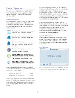
Страница 19: ...nd screens Some screens are password protected to prevent unintended changes There are two levels of security Username is case sensitive User Level Password 9999 Supervisor Level Password 7720 When na...

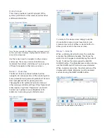
Страница 20: ...ing and alarm settings A few higher level areas require a high level Supervisor password Contact our Customer Service Department for assistance in accessing any restricted menus Overview Screen 1 Over...

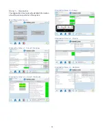
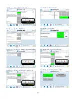
Страница 21: ...detailed information about the various portions of the system Main Diagnostics Screen Diagnostics Screen 1 Circuit 1 Overview Diagnostics Screen 2 Circuit 1 Interlocks Diagnostics Screen 3 Pumps Diagn...

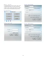
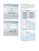
Страница 22: ...s of the control program and provide some level of supervisory control to some operating parameters the control system includes some security level protections Main Security Screen Security Log In Scr...

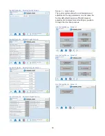
Страница 23: ...ens display the status of the various system inputs and outputs This provides a detailed level of information for monitoring system operation and for diagnosing any performance issues or alarms that a...

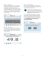
Страница 24: ...al Outputs Screen Menu 1 User Setup The control system allows for customization and adjustment of many parameters In most cases the factory default settings are sufficient however adjustment of parame...

Страница 25: ...etup Screen User Setup Hot Gas Bypass Screen User Setup Pumps Screen User Setup Process Pump VFD Screen User Setup EEV Control Screen User Setup Staging User Setup Stage Order Screen User Setup Discha...

Страница 26: ...er Setup Modbus RTU Screen User Setup Process Temperature Retransmit Screen User Setup Variable Speed Compressor Screen User Setup IP Address Screen User Setup Units Screen User Setup 3 Way Mod Valve...

Страница 27: ...point of the system operation Menu 2 Full Screen Menu 2 System Build This menu allows configuration of the system Use this menu only with the assistances of someone from the Customer Service Departme...

Страница 28: ...Coil 19 1 COND_FAN2_OVLD_OK Bool Coil 20 1 ENABLE_FAN_FS2 Bool Coil 21 1 COND_FAN3_EXISTS Bool Coil 22 1 COND_FAN3_OVLD_OK Bool Coil 23 1 ENABLE_FAN_FS3 Bool Coil 25 1 PULSE_2SEC Bool Coil 26 1 SYSTEM...

Страница 29: ...T Active Bool Coil 94 1 AL_PRB_LIQUID_TEMP Active Bool Coil 95 1 AL_FLOW_SENSOR Active Bool Coil 96 1 AL_PRB_PUMP_PX Active Bool Coil 97 1 AL_CPCOE_COM_FAULT Active Bool Coil 110 1 HIGH_SUPPLY_WATER_T...

Страница 30: ...URN_WATER_HIGH_WARNING_HMI Real HoldingRegister 60 1 WTR_TEMP_BYPASS_TIME_SECONDS Int HoldingRegister 61 1 NO_FLOW_TIME_DELAY_SEC Int HoldingRegister 62 2 FREEZESTAT_SETPOINT Real HoldingRegister 64 2...

Страница 31: ...r 71 1 SUPPLY_WATER_BYPASS_REMIANING Int InputRegister 72 2 SUPPLY_WATER_HIGH_WARNING_HMI Real InputRegister 74 1 SUPPLY_WATER_HIGH_HIGH_FAULT_TIME Int InputRegister 75 2 SUPPLY_WATER_LOW_WARNING_HMI...

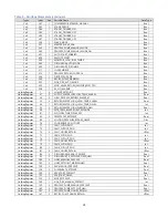
Страница 32: ...206 1 RETRANSMIT_PERCENT Int InputRegister 226 1 CHILLER_STATUS UInt InputRegister 231 2 EVAP_IN_FLUID_HMI Real Table 9 BACNet Parameters Type Object Instance Variable Name Data Type BinaryValue 1 HM...

Страница 33: ...PS Active Bool BinaryValue 57 AL_COND_FAN1_OVLD Active Bool BinaryValue 58 AL_COND_FAN2_OVLD Active Bool BinaryValue 59 AL_COND_FAN3_OVLD Active Bool BinaryValue 60 AL_FANS_ALL_FAULTED Active Bool Bin...

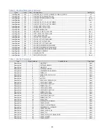
Страница 34: ...ue 112 MASTER_SLAVE_ENA Bool BinaryValue 113 PROCESS_PUMP_MANUAL_MODE Bool BinaryValue 114 PROCESS_PUMP_MANUAL_MODE_ON Bool BinaryValue 115 AUTO_START_ENABLED Bool BinaryValue 116 REMOTE_START Bool Bi...

Страница 35: ...ERCENT Int AnalogValue 166 PROCESS_PUMP_MANUAL_PERCENT Real AnalogValue 167 PROCESS_PUMP_SETPOINT_HMI Real PositiveIntegerValue 168 PROCESS_PUMP_HOURS_RETAIN UDInt PositiveIntegerValue 169 RECIRC_PUMP...

Страница 36: ...IntegerValue 219 NQV_TRIP_LOCKOUT_NUMBER Int IntegerValue 220 NQV_SYSTEM_CONTROL_WORD Int IntegerValue 221 NQV_EV2_03_MAX_FREQUENCY Int IntegerValue 222 NQV_EV2_04_MIN_FREQUENCY Int IntegerValue 223...

Страница 37: ...id refrigerant does not accumulate in the compressor crankcase Connect main power at least 24 hours prior to initial start up CAUTION Wire the unit ground in compliance with local and national codes S...

Страница 38: ...haracteristic Quality Limitation Alkalinity HCO3 70 300 ppm Aluminum Al Less than 0 2 ppm Ammonium NH3 Less than 2 ppm Chlorides Cl Less than 300 ppm Electrical Conductivity 10 500 S cm Free aggressiv...

Страница 39: ...the factory with the Freezestat set at 38 F CAUTION The manufacturer s warranty does not cover the evaporator from freezing It is vital that the Freezestat is set properly Step 6 Turn On Control Powe...

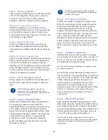
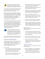
Страница 40: ...uced potential downtime repair costs and extends the useful life of the chiller Once a Week 1 Air Cooled Units Only Check the surface of the air cooled condenser coil for dirt and debris To clean rins...

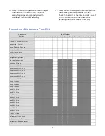
Страница 41: ...ity Week Number 1 2 3 4 5 6 7 8 9 10 11 12 13 Date Clean Air Coils and Inlet Filters Temperature Control Pump Discharge Pressure Coolant Level Glycol Concentration Pump Seal Refrigerant Sight Glass El...

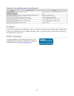
Страница 42: ...10 F Condenser fan motor air cooled units only Replace if faulty Condenser fan cycling control air cooled units only Confirm proper operation replace if faulty Plugged condenser water cooled units onl...

Страница 43: ...ontact refrigeration service technician Refrigeration circuit problem Contact refrigeration service technician Temperature sensor Replace if faulty Drawings Units ship from the factory with drawings i...

Страница 44: ...38...
Страница 45: ...Customer Service Parts Department 847 966 2260 info thermalcare com 847 966 2260 847 966 9358 fax 847 966 2636 847 966 8560 847 966 9358 fax www thermalcare com sales thermalcare com service thermalc...

Отзывы: