


2-6
User Manual PN 84469 Rev L
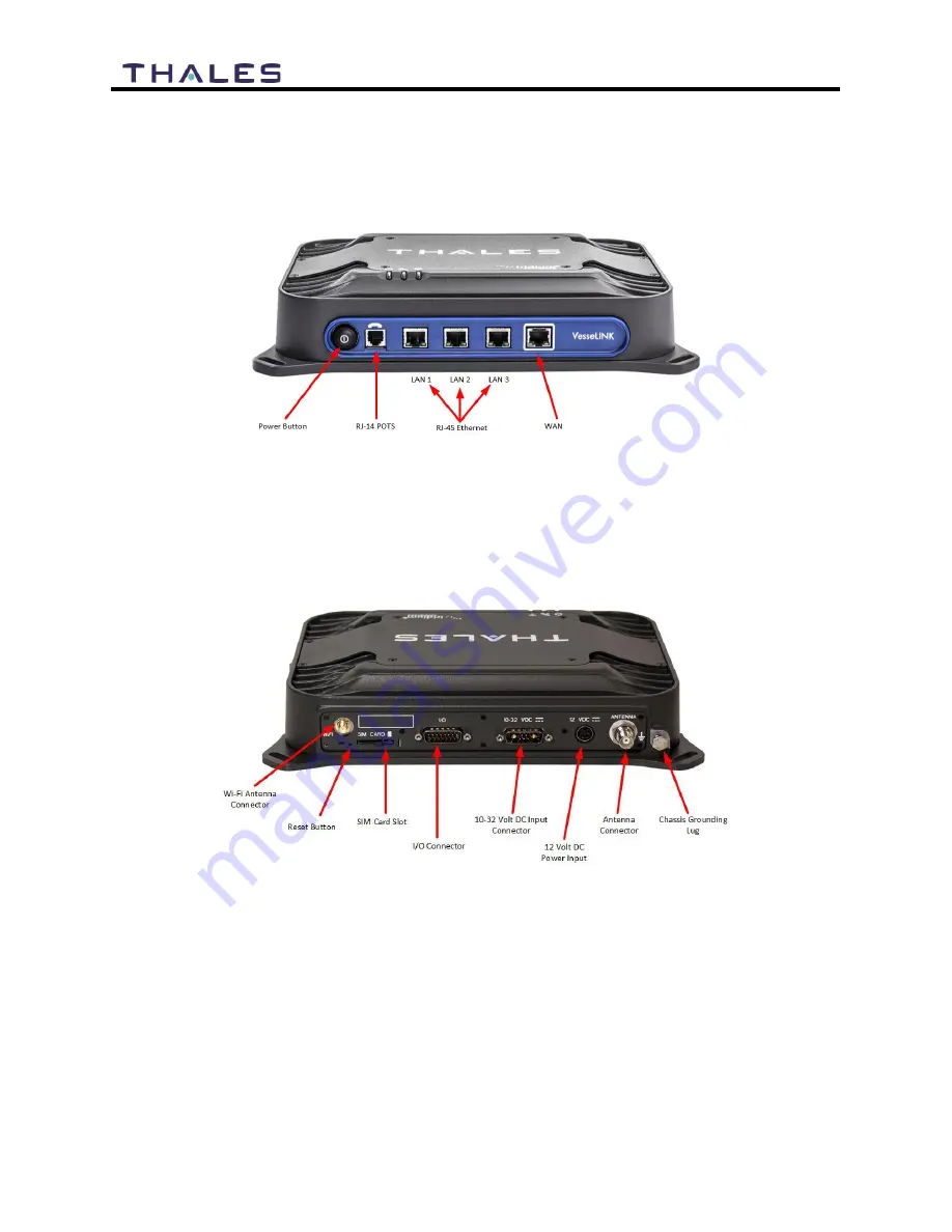
The BDU front panel (left to right) has a main power button, one RJ-14 connector for POTS
(Plain Old Telephone Service) Phone(s), three PoE (Power over Ethernet) RJ-45 connectors for
VoIP phones or Ethernet-based devices, and one WAN (Wide Area Network) connector
primarily used to connect an external cellular modem or VSAT.
Figure 2-6 Below Deck Unit (BDU) Front Panel Detail
The BDU back panel (left to right) has a Wi-Fi antenna connector, reset button, SIM Card slot,
GPIO (I/O) connector, 10-32Volt DC input connector, 12Volt DC power input, antenna
connector, and chassis grounding lug.
Figure 2-7 Below Deck Unit (BDU) Back Panel Detail
Содержание VesseLINK Certus 200
Страница 12: ...xii Uer Manual PN 84469 Rev L ...
Страница 13: ...xiii Uer Manual PN 84469 Rev L ...
Страница 15: ...xv Uer Manual PN 84469 Rev L ...
Страница 16: ...xvi Uer Manual PN 84469 Rev L ...
Страница 17: ...xvii Uer Manual PN 84469 Rev L ...
Страница 18: ...xviii Uer Manual PN 84469 Rev L ...
Страница 28: ...2 8 User Manual PN 84469 Rev L THIS PAGE INTENTIONALLY LEFT BLANK ...
Страница 58: ...4 22 User Manual PN 84469 Rev L Figure 4 25 Settings Wi Fi Screen ...
Страница 62: ...4 26 User Manual PN 84469 Rev L Figure 4 26 Settings LAN Screen ...
Страница 65: ...4 29 User Manual PN 84469 Rev L Figure 4 27 Settings WAN Screen ...
Страница 68: ...4 32 User Manual PN 84469 Rev L Figure 4 28 Settings Phone Screen ...
Страница 78: ...4 42 User Manual PN 84469 Rev L Figure 4 35 Settings Radio Gateway ...
Страница 84: ...4 48 User Manual PN 84469 Rev L Figure 4 37 Settings Secondary Data Flows ...
Страница 94: ...4 58 User Manual PN 84469 Rev L Figure 4 44 System Data Usage Screen Figure 4 45 Reset Data Usage Screen ...