background image


3-4 

User Manual PN 84481 Rev 1 

Making an Emergency Call


An Emergency Call can be made in two ways; either by selecting the Emergency Icon in the 
LINK Application or by pressing and holding the Emergency Button at the top of the Handset. 
 
Before either of these methods is used, the call number must first be configured.  To do this: 

1.


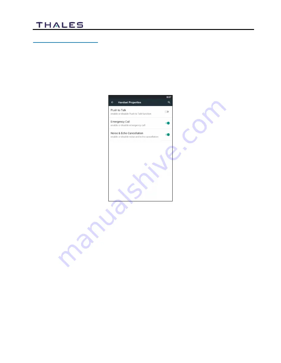
First select the SETTINGS icon (not within the LINK Application).  Select HANDSET 
PROPERTIES and select EMERGENCY CALL to enable. It will turn green when 
enabled. It is gray when disabled. 


Figure 3-4 Enable Emergency Call (Shown Enabled) 


2.


Within the LINK application, select the SETTINGS icon, then PREFERENCES, then 
CONFIGURE.  


3.


To configure the Emergency Number, select EMERGENCY NUMBER.  A keypad will 
be displayed. Enter the number (including 9) that you want to call when in an 
Emergency. (Note – to remove the keypad, press the left Android button.) 


Содержание SureLINK

Страница 1: ...ument contains technology controlled for export by the U S Department of Commerce in accordance with Export Administration Regulations Diversion contrary to U S law prohibited JULY 2019 JUNE 2017 JUNE 2017 JUNE 2017 COPYRIGHT 2019 THALES DEFENSE SECURITY INC ALL RIGHTS RESERVED ...

Страница 2: ...e in accordance with Export Administration Regulations EAR Diversion contrary to U S law prohibited Include this notice with any reproduced portion of this document WARNING INFORMATION SUBJECT TO EXPORT CONTROL RESTRICTIONS This document contains technology controlled for export by the U S Department of Commerce in accordance with Export Administration Regulations EAR Diversion contrary to U S law...

Страница 3: ...tions of Thales or any third party software providers except for the normal nonexclusive royalty free license to use that arises by operation of law in the sale of a product Content Copyright User is exclusively responsible for the use of this product including proper use of third party copyrighted materials If the User violates these terms the User agrees to defend indemnify and hold Thales harml...

Страница 4: ... SET UP 2 3 Installing the SureLINK Handset 2 3 Mounting the SureLINK Handset 2 4 Weather Proofing the Cord 2 4 Getting Started Plug And Play 2 5 Link Application Menu Components 2 10 Link Application Settings 2 1 OPERATION 3 1 SURELINK HANDSET OPERATION 3 1 Making a Call 3 1 Receiving a Call 3 3 Making an Emergency Call 3 4 MANAGEMENT PORTAL 3 6 TECHNICAL SPECIFICATIONS 4 1 TECHNICAL SPECIFICATIO...

Страница 5: ...8 SETTINGS MAIN SCREEN 2 8 FIGURE 2 9 LINK APPLICATIONS TAB BUTTONS 2 10 FIGURE 2 9 LINK APPLICATION SETTINGS 2 1 FIGURE 3 1 THALES HANDSET DIAL PAD SCREEN 3 2 FIGURE 3 2 HANDSET CALL SCREEN 3 2 FIGURE 3 3 INCOMING CALL SCREEN 3 3 FIGURE 3 4 ENABLE EMERGENCY CALL SHOWN ENABLED 3 4 FIGURE 3 5 ENTER THE EMERGENCY NUMBER 3 5 FIGURE 3 6 EMERGENCY 3 6 List of Tables TABLE 1 1 THALES SURELINK HANDSET 1 ...

Страница 6: ...y operators or technicians Covers must remain in place at all times to maintain the warranty terms WARNING DO NOT OPERATE IN AN EXPLOSIVE ATMOSPHERE This equipment is not designed to be operated in explosive environments or in the presence of combustible fumes Operating this or any electrical equipment in such an environment represents an extreme safety hazard ...

Страница 7: ...o the Management Portal on the terminal unit refer to either of the following user guides Thales MissionLINK User Manual Document 84468 Thales VesseLINK User Manual Document 84469 NOTE This user manual is intended for anyone who intends to operate and configure the Thales SureLINK Handset It however cannot cover all topics and advanced features For questions or topics that are not covered in this ...

Страница 8: ...Contents The following list of equipment cones standard in the SureLINK kit and can be purchased individually as spares depending on your requirements and or needs Refer to Figure 1 1 Table 1 1 Thales SureLINK Handset Part Number Description 1100818 501 Kit Thales SureLINK Handset Qty Part Number Description 1 1600913 1 Thales SureLINK Handset 1 40525 001 Button Clip Holder 1 855046 001 RC Cable A...

Страница 9: ...ss display used to select the LINK icon and navigate through the screens Standard Phone Microphone Microphone port on bottom used during standard phone calls Android Buttons The three buttons perform the following functions Left button back button returns to previous screen Center button Home Button quick press returns to Home screen or if display is off turns on the display Long press shuts off d...

Страница 10: ...he Handset during a speaker phone call Standard Phone Audio Port Audio port used for standard voice calls Note that the audio port is not in the center of the Handset so for optimal sound make sure the port is correctly aligned with the ear Emergency Button Dedicated button that when pressed and held enables an emergency call or message to be made to a phone number or email address PTT Button Used...

Страница 11: ...le Ethernet connector between the female Ethernet connector at the end of the coil cord and any one of the Ethernet LAN connectors on the Terminal TU Below Deck Unit BDU Figure 2 2 Ethernet Cable Connection to Handset 2 Once the SureLINK Handset is plugged in the screen will power up This may take a minute or so The Handset is now ready to use NOTE The Handset has been preconfigured to operate on ...

Страница 12: ...et If mounting is desired pre drill and screw the mounting clip into a hard surface using the provided two screws The button on the backside of the SureLINK Handset will securely fit into the clip for Handset storage while not in use Weather Proofing the Cord The connection at the end of coil cord can also be more weather resistant by crimping a new male Ethernet connector on the cable once it is ...

Страница 13: ...BUTTON 1 Press the center Android button to illuminate the screen The Thales SureLINK home screen will appear or it may automatically open the LINK app and display the Dial Pad To open select the icon at the bottom center of the Home Screen Figure 2 4 Thales SureLINK Home Screen 2 The next screen will be the Handset Application Display From this screen you will select the LINK Application ...

Страница 14: ...pen the LINK Application select the LINK icon 4 When you first open the LINK Application for the first time the Dial Pad will be the first screen that appears To enter the Handset Portal press the PORTAL icon at the bottom left of the screen Figure 2 6 Thales Handset Dial Pad Screen ...

Страница 15: ... this screen is the same as you will see the TU BDU Management Portal Figure 2 7 Thales Link Portal NOTE For information pertaining to the Management Portal on the terminal unit refer to either of the following user guides Thales MissionLINK User Manual Document 84468 Thales VesseLINK User Manual Document 84469 ...

Страница 16: ...tive Brightness enable disable Set Sleep mode 15 secs 30 sec 1 minute 2 minutes 5 minutes and 10 minutes Set Font size Small Normal Large and Huge Sound Notification When selected the user can Set the volume level for Media Set the volume level for Notification Set the notification ringtone Handset Properties When selected the user can Push To Talk PTT Enable Disable PTT Emergency Call Enable Disa...

Страница 17: ...nput Methods Keyboard type and Android keyboard settings System Time and Date When selected the user can Automatically set date and time Automatically set time zone Select 24 hour format Choose date format About Handset When selected the following information is displayed System Updates IP Address MAC Address Unit S N Model Android Version Kernel Version Build Number Reboot device ...

Страница 18: ...it refer to either of the following user guides Thales MissionLINK User Manual Document 84468 Thales VesseLINK User Manual Document 84469 LINK Application Tab Buttons Figure 2 9 LINK Applications Tab Buttons Table 2 3 LINK Application Tab Buttons ICON Description Portal Tab Button Dial Pad Tab Button Settings Tab Button Emergency Tab Button ...

Страница 19: ...Tab Button When selected the phone key pad will be displayed Telephone calls are made from this screen Refer to Figure 3 1 Settings Tab Button Provides information relating accounts existing and new and preferences configure Management Portal name and password setting up the Emergency call number Refer to Figure 2 9 Emergency Tab Button Selecting this tab will open the Emergency Call screen Refer ...

Страница 20: ...use of mobile data and enable disable the account User Details Name of the device username and Domain Default to sip thaleslink Authentication username and password New Account Allows a new account to be established General information enter the new account name enable the use of mobile data and enable disable the account User details enter the Display Name Username and Domain Authentication enter...

Страница 21: ...User Manual PN 84481 Rev 1 Section Parameters Audio Codecs Provides information relating to Mobile Data Audio Codecs and Wi Fi Audio Codecs Information only About About Displays current version information ...

Страница 22: ...ound Iridium Lines found in the Management Portal in SETTINGS PHONE If the default configuration of the terminal has not changed the Handset is set up to operate on Extension 1002 using the Iridium phone number corresponding to that extension The Android device IP address can be found by selecting the SETTINGS icon not within the LINK Application then select ABOUT HANDSET To reboot the handset pre...

Страница 23: ...then the number to be called and press Call Once connected if speakerphone mode is desired follow instructions on the screen to first enable the keypad and then select speaker You can also bring up the keypad mute the Handset put the call on hold or add a caller Figure 3 2 Handset Call Screen ...

Страница 24: ...rom a caller over the satellite network the caller would dial the Iridium number that the Handset is mapped to Select Answer when the Handset Rings Figure 3 3 Incoming Call Screen Example Once connected if speakerphone mode is desired select the SPEAKER icon You can also bring up the keypad mute the Handset put the call on hold or add a caller Refer to Figure 3 2 NOTE To change the volume press an...

Страница 25: ...First select the SETTINGS icon not within the LINK Application Select HANDSET PROPERTIES and select EMERGENCY CALL to enable It will turn green when enabled It is gray when disabled Figure 3 4 Enable Emergency Call Shown Enabled 2 Within the LINK application select the SETTINGS icon then PREFERENCES then CONFIGURE 3 To configure the Emergency Number select EMERGENCY NUMBER A keypad will be display...

Страница 26: ...initiated after 5 seconds if not canceled Method 2 Within the LINK application select the EMERGENCY icon Press the Green button on the screen SEND EMERGENCY SIGNAL A red CANCEL button appears on the screen with a 5 second countdown Press CANCEL if the call needs to be canceled Emergency call will be initiated after 5 seconds if not canceled NOTE If Emergency has not been enabled in the Settings an...

Страница 27: ...dinates MANAGEMENT PORTAL The LINK application can be used to configure and monitor the MissionLINK and VesseLINK systems through the Management Portal NOTE The user name and password must be correct in the LINK Settings icon To access the Management portal within the LINK application select the PORTAL icon It may take a minute to load Make sure to Login to access Settings and other protected Admi...

Страница 28: ...ns Category Technical Specification Operating Temperature 20 C to 55 C Regulatory FCC Part 15 Class B EN61000 4 Humidity 95 at 40 C Audio Level loud speaker 90 db SPL Power Required POE 6 5 watts Display 4 diagonal 480 x 800 pixels Vibration MIL STD 810G Ingress Protection IP65 Size Weight 5 L x 3 W x 1 D 10 5 oz ...

Страница 29: ...4 2 User Manual PN 84481 Rev 1 THIS PAGE INTENTIONALLY LEFT BLANK ...

Страница 30: ...uts GPS Global Positioning System HGA High Gain Antenna HRLP High Speed Radio Link Protocol HTTP Hypertext Transfer Protocol ICMP Internet Control Message Protocol IP Internet Protocol ITU International Telecommunications Union LAN Local Area Network LED Light Emitting Diode LEO Low Earth Orbiting LGA Low Gain Antenna LOS Line of Site MO Mobile Originated msec Milliseconds MT Mobile Terminated NAS...

Страница 31: ...ement Bus SV Satellite Vehicle TCP Transmission Control Protocol TDSI Thales Defense Security Inc TLS Transport Layer Security TU Terminal Unit UDP User Datagram Protocol UL DL Uplink Downlink VAD Voice Activity Detection VLAN Virtual Local Area Network VoIP Voice of Internet Protocol WAN Wide Area Network Wi Fi Wireless Network WPA2 PSK Wi Fi Protected Access 2 Pre Shared Key ...

Страница 32: ......

Страница 33: ...l PN 84481 Rev 1 Thales Defense Security Inc 22605 Gateway Center Drive Clarksburg MD 20871 Toll Free 1 800 324 6089 Phone 240 864 7000 Fax 240 864 7920 Email Customer Service thalesdsi com Website www thalesdsi com ...

Отзывы: