


Texmate, Inc. Tel. (760) 598-9899 • www.texmate.com
Page 30
Apr-21-2016 DI_602A 320 DS (NZ313)_April 2016
To enter press
P
and
buttons at the same time
[SP_1]
Setpoint Activation Values
[SP_2]
[SP_3]
[SP_4]
[SP_5]
[SP_6]
Enter these menus to set setpoint
(SP) activation values
Setpoint & Relay Control Function Settings
Setpoint Programming Mode
P
SP1
SP3
SP4
SP5
SP6
SP2
F1
F2
P
Operational Display
SP1
SP3
SP4
SP5
SP6
SP2
F1
F2
P
Operational Display
P
P
P
P
P
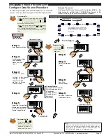
Setpoint Programming Mode Logic Diagram
Setpoint 1
[SPC_1]
Setpoint 2
[SPC_2]
Setpoint 3
[SPC_3]
Setpoint 4
[SPC_4]
Setpoint 5
[SPC_5]
Setpoint 6
[SPC_6]
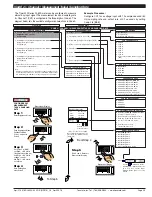
Enter these menus to config-
ure SP control values
P
P
P
P
P
P
The
Setpoint and
Relay Control
Settings
diagram
on Pages 34 and
35 shows the
three digit config-
uration settings
that are applied
individually to
each setpoint.
See Page 33 for
an example proce-
dure to configure a
setpoint for simple
relay functions.
Setpoint 1
Default Setting = 180000
Setpoint 2
Default Setting = –180000
Setpoint 3
Default Setting = 50000
Setpoint 4
Default Setting = –50000
Setpoint 5
Default Setting = 100000
Setpoint 6
Default Setting = –100000
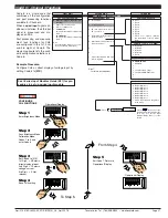
Setpoint Programming Mode
All setpoint activation and control settings are selected and configured using
the front panel buttons in the
setpoint programming mode
. Or, software
configured via the
meter configuration utility program
if the meter is con-
nected to a PC through the serial port. The meter has six software driven
setpoints, independently configured to operate within the total span range of
the meter and the selected input module.
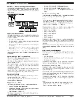
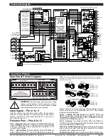
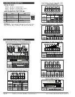
Relay Output Modules
Four standard relay output module options provide a selection of 16 relay
configuration options for DI-50 meters.
Three electromechanical relay output modules support a combination of 4/5
A Form A and 9/10 A Form C relays providing 12 configuration options. A
solid state relay (SSR) output module supports 300 V, 210 mA DC SSRs.
A 22 opto-isolated I/O plug-in module can support six inputs and up to 16
outputs. The standard plug-in module has six inputs and six outputs that can
be extended to 16 outputs with a 10 output add-on board.
Setpoint Programming Mode
See the Setpoint Programming Mode Logic Diagram opposite.
The setpoint programming mode is entered by pressing the meter’s
P
and
buttons at the same time.
Setpoint Activation Values
Each setpoint activation value is individually programmed. Setpoint acti-
vation values can be set within the total span range of the meter and the
selected input module.
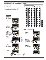
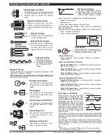
Setpoint and Relay Control Settings
See the Setpoint and Relay Control Settings diagram on Pages 34 and 35.
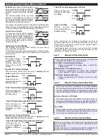
The control settings provide access to the following setpoint and relay func-
tions for configuration using the meter’s 1st, 2nd, and 3rd digits:
•
1st Digit
– Relay Energize Functions.
•
2nd Digit
– Setpoint Activation Source.
•
3rd Digit
– Setpoint Delay, Timer, and Reset and Trigger Functions.
Output Module
Carrier Board
Max Six
4 A Form A
Max Two
4 A Form A
Max Two
9 A Form C
Max Four
210 mA
(DC Only)
Max Four
5 A Form A
320 Series Relay Output Module Options
SSRs
Electromechanical Relays
Standard I/O
Plug-in Module
(6 in/6 out)
Mounts
on top
Digital Outputs
Add-on Board
(10 outputs)
Optional Opto-isolated
22 I/O Plug-in Module


