Texmate, Inc. Tel. (760) 598-9899 • www.texmate.com
Page 4
FL-B101Q-DCA _ FL-B01Q-DCV (d0084)
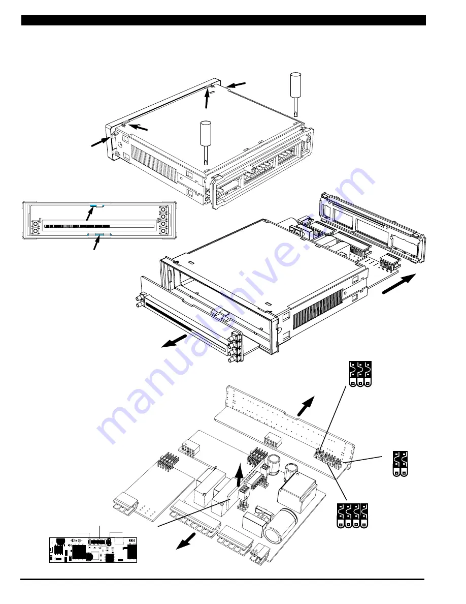
The mode select headers are located on the Display Driver Board assembly. To change any of the modes, it is best to remove the
Display Driver Board assembly from the case. Before removing the Display Driver Board assembly from the front of the case it is
necessary to remove the rear cover and slide the main board back an inch, or remove it, to disengage the pin and socket connector
between the main board and the display assembly.
Step 2
Remove the rear cover plate
by pressing down lightly with a
small flat bladed screw driver
to release two plastic catches,
on either side of the case and
levering backwards.
Step 4
Starting with the top first, insert a
small flat bladed screw driver and
carefully lever the plastic catch up
and tilt the Display Board assembly
forward. Then repeat this action
with the bottom catches.
Step 5
Remove the entire Display Board
assembly by sliding it out of case.
Opening the Case to Access Mode Select Headers
INPU
T SIGNAL
CONDITI
ONER
MAIN BOARD
DISPLA
Y BOARD
DRI
VER BOARD
Meter Exploded view
Optional 16 Bit Isolated Analog Output Module
4 to 20 mA (0 to 20 mA)
Selection Position
0 to 10 V DC
Selection Position
Analog Output
Selection Header
CH1
CH2
Standard or
Center Zero
Display Mode
Select Header
1
3
2
Operating Mode
Select Header
1
3 4
2
Relay Activation Mode
Select Header
b
a
c
d
Front view with bezel and
scale faceplate removed.
Step 1
Remove the front bezel by
lightly levering the plastic
catches up and forward in
the a b c d sequence shown.
Then remove the cover and
scale faceplate.
Step 3
Slide the Main Board back
approximately 1” to disengage
the pin and socket connection
to the Display Driver
Board.


