1
1
SC
19
PID
P
I
D
1
8
1
4
1 z
1 z
1000
G
(z)
K
K
K
2
KCOMP 2
1 z
1 2
z
2
(PRD 1)
-
-
-
-
-
-
æ
ö
+
-
=
+
+
´
´
´
´
ç
÷
ç
÷
-
-
´ a ´
´
+
è
ø
Monitoring, Re-configuring and Re-tuning with Designer GUI
14.4.2
Current Loop Re-Tuning
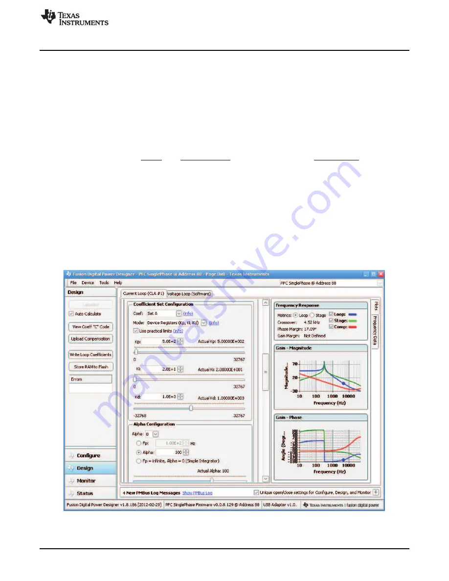
The current loop PID coefficients can be re-tuned following the approaches described in section 1.4. Scroll
down the window that is shown in
, then
is obtained.
shows the current loop compensation details. There are two sets of PID coefficients used in the
current control loop, Set A and Set B. In
Set A is shown. The corresponding bode plots are
shown on the left in
Coefficients of Set A are used when input line voltage is between 90 V
AC
and 160 V
AC
. Coefficients of Set
B are used when input line voltage is above 160 V
AC
till the maximum input of 264 V
AC
.
The actual PID control makes re-scale of the values shown in
when used inside the UCD3138.
(18)
PRD is a threshold value used to generate DPWM cycle ending point. The DPWM is centered on a period
counter which counts up from 0 to PRD, and then is reset and starts over again. In the single-phase PFC
design, KCOMP is set up equal to PRD.
In the current control page of the Design, PID coefficients can be re-tuned. The GUI also provides
conversion results from PID coefficients to the zeros and the pole by clicking Mode to select a
corresponding conversion. One can also change the zeros and the poles and then use the GUI to convert
to PID coefficients by clicking Mode to select back to K
P
, K
I
, and K
D
. Be aware that from the two zeros can
be complex conjugates. When a set of PID coefficients does make complex conjugate zeros, the GUI
pumps up a message to notify that Q and
ω
r have to be generated instead of real zeros. In this case, the
users may need to calculate the complex conjugate zeros based on
Figure 48. Current Loop Re-Tuning
53
SLUU885B – March 2012 – Revised July 2012
Digitally Controlled Single-Phase PFC Pre-Regulator
Copyright © 2012, Texas Instruments Incorporated


