3.4.7
Recharging the Battery Packs
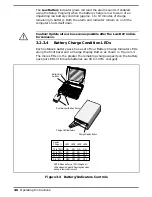
A standalone battery charger option is available to charge notebook battery
packs. The battery packs may also be charged in the notebook as follows:
1.
Install the battery pack in your computer (if not already installed).
2.
Connect the AC Adapter as described in Section 2. The LEDs on the
battery pack(s) will gradually light starting from the left. When all
four LEDs on the battery pack light, this indicates that the battery
pack is at least 90% charged. All four LEDs extinguish when the
battery is 100% charged.
3.
To fully charge the battery packs, leave then charging in the Notebook
for at least another 90 minutes after all four battery LED’s light.
3.4.8
Running the DOS-Based Setup
Program
To run the DOS-Based Setup program, simultaneously press the
Fn-ESC
keys. This program allows you to modify time and date, power savings
settings, define the startup condition of the keyboard and screen and other
functions such as defining drive types, set up com ports, etc.
A System Information feature (accessed by pressing the
F2 key
) gives you
such information as Processor Type, BIOS version number, serial and
parallel port addresses, etc.
n
Note:
To run the Windows-based Setup Program, get into Windows and
click on the TISETUP icon in the Notebook Group.
3.4.9
Backing Up Your System Software
When you power up the notebook, it automatically runs the Setup program
and temporarily halts in the Setup Menu. Use the Up/Down Arrow keys to
highlight
System Maintenance
and press the
Enter
key to select the
System Maintenance utilities. You are then prompted through the backup
procedure.
n
Note
: You will need 22 diskettes (23 for international models) to back up the
system software. These can be unformatted as the system automatically for-
mats the diskettes.
3.4.10 Restoring Missing System Files
When you power up the Notebook, it automatically checks for certain key
files that must be present for normal system operation (E.G.
COMMAND.COM, IO.SYS, MSDOS.SYS, etc.). If any of these files are
accidently erased as indicated by error message, insert the System Recovery
Diskette and reboot the system. The missing files will automatically be
retrieved from floppy.
3-10
Operating Instructions
Содержание TravelMate 5000 Series
Страница 1: ...Maintenance Manual TravelMate 5000 Series Notebook Computers 9786166 0001 March 1995 ...
Страница 47: ...Figure 1 16 TM5000 Series Functional Block Diagram 1 30 General Description ...
Страница 95: ...Figure 4 2 Notebook Detailed Block Diagram Troubleshooting Procedures 4 3 ...
Страница 149: ...Figure 6 4 Main Board P54 75MHz P N 9798803 0001 Sheet 2 of 2 6 14 Illustrated Parts Listing ...
Страница 161: ...Figure 6 5 Figure 6 5 PCMCIA Sound Board P N 9786205 0001 Sheet 1 of 2 6 26 Illustrated Parts Listing ...
Страница 162: ...Figure 6 6 Figure 6 5 PCMCIA Sound Board P N 9786205 0001 Sheet 2 of 2 Illustrated Parts Listing 6 27 ...
Страница 172: ...Figure 6 7 Keyscan Board P N 9786209 0001 Illustrated Parts Listing 6 37 ...
Страница 180: ...Figure 6 11 Inverter Board P N 9786134 0001 Illustrated Parts Listing 6 45 ...
Страница 185: ...Figure 6 12 DAB Board P N 9786273 0001 6 50 Illustrated Parts Listing ...
Страница 188: ...Figure 7 1 Figure 7 1 Main Board Part No 9798803 Logic Diagram Sheet 1 of 22 7 2 Schematic Diagrams ...
Страница 189: ...Figure 7 1 Figure 7 1 Main Board Part No 9798803 Logic Diagram Sheet 2 of 22 Schematic Diagrams 7 3 ...
Страница 190: ...Figure 7 1 Figure 7 1 Main Board Part No 9798803 Logic Diagram Sheet 3 of 22 7 4 Schematic Diagrams ...
Страница 191: ...Figure 7 1 Figure 7 1 Main Board Part No 9798803 Logic Diagram Sheet 4 of 22 Schematic Diagrams 7 5 ...
Страница 192: ...Figure 7 1 Figure 7 1 Main Board Part No 9798803 Logic Diagram Sheet 5 of 22 7 6 Schematic Diagrams ...
Страница 193: ...Figure 7 1 Figure 7 1 Main Board Part No 9798803 Logic Diagram Sheet 6 of 22 Schematic Diagrams 7 7 ...
Страница 194: ...Figure 7 1 Figure 7 1 Main Board Part No 9798803 Logic Diagram Sheet 7 of 22 7 8 Schematic Diagrams ...
Страница 195: ...Figure 7 1 Figure 7 1 Main Board Part No 9798803 Logic Diagram Sheet 8 of 22 Schematic Diagrams 7 9 ...
Страница 196: ...Figure 7 1 Figure 7 1 Main Board Part No 9798803 Logic Diagram Sheet 9 of 22 7 10 Schematic Diagrams ...
Страница 197: ...Figure 7 1 Figure 7 1 Main Board Part No 9798803 Logic Diagram Sheet 10 of 22 Schematic Diagrams 7 11 ...
Страница 198: ...Figure 7 1 Figure 7 1 Main Board Part No 9798803 Logic Diagram Sheet 11 of 22 7 12 Schematic Diagrams ...
Страница 199: ...Figure 7 1 Figure 7 1 Main Board Part No 9798803 Logic Diagram Sheet 12 of 22 Schematic Diagrams 7 13 ...
Страница 200: ...Figure 7 1 Figure 7 1 Main Board Part No 9798803 Logic Diagram Sheet 13 of 22 7 14 Schematic Diagrams ...
Страница 201: ...Figure 7 1 Figure 7 1 Main Board Part No 9798803 Logic Diagram Sheet 14 of 22 Schematic Diagrams 7 15 ...
Страница 202: ...Figure 7 1 Figure 7 1 Main Board Part No 9798803 Logic Diagram Sheet 15 of 22 7 16 Schematic Diagrams ...
Страница 203: ...Figure 7 1 Figure 7 1 Main Board Part No 9798803 Logic Diagram Sheet 16 of 22 Schematic Diagrams 7 17 ...
Страница 204: ...Figure 7 1 Figure 7 1 Main Board Part No 9798803 Logic Diagram Sheet 17 of 22 7 18 Schematic Diagrams ...
Страница 205: ...Figure 7 1 Figure 7 1 Main Board Part No 9798803 Logic Diagram Sheet 18 of 22 Schematic Diagrams 7 19 ...
Страница 206: ...Figure 7 1 Figure 7 1 Main Board Part No 9798803 Logic Diagram Sheet 19 of 22 7 20 Schematic Diagrams ...
Страница 207: ...Figure 7 1 Figure 7 1 Main Board Part No 9798803 Logic Diagram Sheet 20 of 22 Schematic Diagrams 7 21 ...
Страница 208: ...Figure 7 1 Figure 7 1 Main Board Part No 9798803 Logic Diagram Sheet 21 of 22 7 22 Schematic Diagrams ...
Страница 209: ...To Be Supplied Figure 7 1 Figure 7 1 Main Board Part No 9798803 Logic Diagram Sheet 22 of 22 Schematic Diagrams 7 23 ...
Страница 210: ...Figure 7 2 Figure 7 2 PCMCIA Sound Board P N 9786205 Logic Diagram Sheet 1 of 12 7 24 Schematic Diagrams ...
Страница 211: ...Figure 7 2 Figure 7 2 PCMCIA Sound Board P N 9786205 Logic Diagram Sheet 2 of 12 Schematic Diagrams 7 25 ...
Страница 212: ...Figure 7 2 Figure 7 2 PCMCIA Sound Board P N 9786205 Logic Diagram Sheet 3 of 12 7 26 Schematic Diagrams ...
Страница 213: ...Figure 7 2 Figure 7 2 PCMCIA Sound Board P N 9786205 Logic Diagram Sheet 4 of 12 Schematic Diagrams 7 27 ...
Страница 214: ...Figure 7 2 Figure 7 2 PCMCIA Sound Board P N 9786205 Logic Diagram Sheet 5 of 12 7 28 Schematic Diagrams ...
Страница 215: ...Figure 7 2 Figure 7 2 PCMCIA Sound Board P N 9786205 Logic Diagram Sheet 6 of 12 Schematic Diagrams 7 29 ...
Страница 216: ...Figure 7 2 Figure 7 2 PCMCIA Sound Board P N 9786205 Logic Diagram Sheet 7 of 12 7 30 Schematic Diagrams ...
Страница 217: ...Figure 7 2 Figure 7 2 PCMCIA Sound Board P N 9786205 Logic Diagram Sheet 8 of 12 Schematic Diagrams 7 31 ...
Страница 218: ...Figure 7 2 Figure 7 2 PCMCIA Sound Board P N 9786205 Logic Diagram Sheet 9 of 12 7 32 Schematic Diagrams ...
Страница 219: ...Figure 7 2 Figure 7 2 PCMCIA Sound Board P N 9786205 Logic Diagram Sheet 10 of 12 Schematic Diagrams 7 33 ...
Страница 220: ...Figure 7 2 Figure 7 2 PCMCIA Sound Board P N 9786205 Logic Diagram Sheet 11 of 12 7 34 Schematic Diagrams ...
Страница 221: ...Figure 7 2 Figure 7 2 PCMCIA Sound Board P N 9786205 Logic Diagram Sheet 12 of 12 Schematic Diagrams 7 35 ...
Страница 222: ...Figure 7 3 Figure 7 3 Keyscan Board P N 9786209 Logic Diagram Sheet 1 of 5 7 36 Schematic Diagrams ...
Страница 223: ...Figure 7 3 Figure 7 3 Keyscan Board P N 9786209 Logic Diagram Sheet 2 of 5 Schematic Diagrams 7 37 ...
Страница 224: ...Figure 7 3 Figure 7 3 Keyscan Board P N 9786209 Logic Diagram Sheet 3 of 5 7 38 Schematic Diagrams ...
Страница 225: ...Figure 7 3 Figure 7 3 Keyscan Board P N 9786209 Logic Diagram Sheet 4 of 5 Schematic Diagrams 7 39 ...
Страница 226: ...Figure 7 3 Figure 7 3 Keyscan Board P N 9786209 Logic Diagram Sheet 5 of 5 7 40 Schematic Diagrams ...
Страница 227: ...Figure 7 4 Figure 7 4 Sleep Switch Board P N 9786148 Logic Diagram Sheet 1 of 1 Schematic Diagrams 7 41 ...
Страница 228: ...Figure 7 5 Figure 7 5 IR Board P N 9798813 Logic Diagram Sheet 1 of 2 7 42 Schematic Diagrams ...
Страница 229: ...Figure 7 5 Figure 7 5 IR Board P N 9798813 Logic Diagram Sheet 2 of 2 Schematic Diagrams 7 43 ...
Страница 230: ...Figure 7 6 Figure 7 6 LED Board P N 9796128 Logic Diagram Sheet 1 of 2 7 44 Schematic Diagrams ...
Страница 231: ...Figure 7 6 Figure 7 6 LED Board P N 9796128 Logic Diagram Sheet 2 of 2 Schematic Diagrams 7 45 ...
Страница 232: ...Figure 7 7 Figure 7 7 8 16 MB RAM Exp Board P N 9798816 Logic Diagram Sheet 1 of 1 7 46 Schematic Diagrams ...
Страница 233: ...Figure 7 8 Figure 7 8 Inverter Board P N 9796134 Logic Diagram Sheet 1 of 2 Schematic Diagrams 7 47 ...
Страница 234: ...Figure 7 8 Figure 7 8 Inverter Board P N 9796134 Logic Diagram Sheet 2 of 2 7 48 Schematic Diagrams ...
Страница 235: ...Figure 7 8 Figure 7 9 Display Adapter Board P N 9786273 Logic Diagram Sheet 1 of 3 Schematic Diagrams 7 49 ...
Страница 236: ...Figure 7 9 Figure 7 9 Display Adapter Board P N 9786273 Logic Diagram Sheet 2 of 3 7 50 Schematic Diagrams ...
Страница 237: ...Figure 7 9 Figure 7 9 Display Adapter Board P N 9786273 Logic Diagram Sheet 3 of 3 Schematic Diagrams 7 51 ...
Страница 239: ...Figure A 1 Code Page 437 United States A 2 Character Sets ...
Страница 240: ...Figure A 2 Code Page 850 Multilingual Character Sets A 3 ...
Страница 241: ...Figure A 3 Code Page 863 Canadian French A 4 Character Sets ...
Страница 242: ...Figure A 4 Code Page 865 Nordic Character Sets A 5 ...
Страница 286: ...Printed in U S A ...


