Texas Instruments TPSM8286 AA0 Series Скачать руководство пользователя страница 4

2 Setup

This section describes how to properly use the TPSM8286xAA0xEVM.

2.1 Setup

To operate the EVM, set jumper JP1 between ON and EN to turn on the device as shown in 

Input, Output 

Connector and Jumper Descriptions

. Connect the input supply to J1 and connect the load to J2.

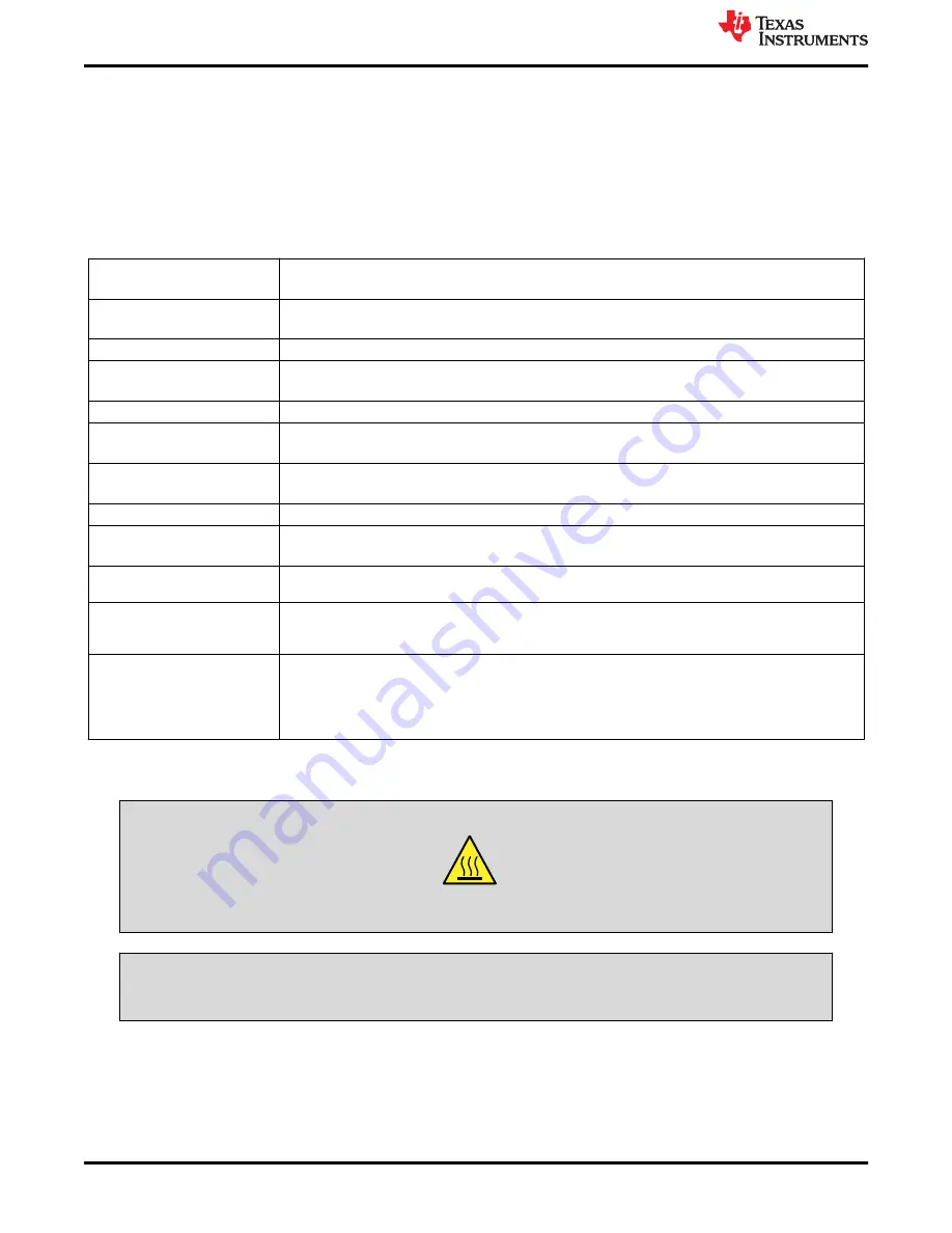
2.2 Input, Output Connector and Jumper Descriptions

J1 – VIN/GND

Input and return connections from the input supply for the EVM.
This connector supports currents over 3 A and accepts up to 16 AWG wire.

J2 – VOUT/GND

Input and return connections from the EVM to the load.
This connector supports currents over 3 A and accepts up to 16 AWG wire.

J3 – PG/GND

The PG output appears on pin 2 of this header with ground on pin 1.

J4, Pin 1 and 2 – VIN

Positive input connection from the input supply for the EVM
Do not use for currents above 3 A.

J4, Pin 3 and 4 – S+/S–

Input voltage sense connections. Measure the input voltage at this point.

J4, Pin 5 and 6 – GND

Input return connection from the input supply for the EVM.
Do not use for currents above 3 A.

J5, Pin 1 and 2 – VOUT

Output voltage connection
Do not use for currents above 3 A.

J5, Pin 3 and 4 – S+/S–

Output voltage sense connections. Measure the output voltage at this point.

J5, Pin 5 and 6 – GND

Output return connection
Do not use for currents above 3 A.

JP1 – EN

EN pin input jumper. Place the supplied jumper across ON and EN to turn on the module. Place the 
jumper across OFF and EN to turn off the module.

JP2 – PG Pullup Voltage

PG pin pullup voltage jumper. Place the supplied jumper on JP2 to connect the PG pin pullup resistor to 
VOUT. Alternatively, the jumper can be removed and a different voltage can be supplied on pin 1 to pull 
up the PG pin to a different level. This externally applied voltage must remain below 6 V.

JP3 – VSET/MODE

VSET/MODE pin input jumper. Place the supplied jumper across PWM and VSET/MODE to operate the 
IC in Forced PWM mode. Place the jumper across PFM/PWM and VSET/MODE to operate the IC in 
Auto PFM/PWM mode. Remove the jumper to operate the IC with a fixed output voltage, which is set by 
R4.
For the fixed output voltage configuration, R4 must be installed, R2 removed, and R1 shorted.

3 Safety Instructions

WARNING

Hot surface. Contact may cause burns. Do not touch.

WARNING

High currents may be present on the input and output. Use connectors J1 and J2 if the current exceeds 3 A.

Setup

www.ti.com

4

TPSM8286xAA0xEVM Evaluation Module

SLVUCB0A – SEPTEMBER 2021 – REVISED NOVEMBER 2022

Submit Document Feedback

Copyright © 2022 Texas Instruments Incorporated

Содержание TPSM8286 AA0 Series

Страница 1: ...ifications 2 2 Setup 4 2 1 Setup 4 2 2 Input Output Connector and Jumper Descriptions 4 3 Safety Instructions 4 4 Test Results 5 5 Board Layout 7 6 Schematic and Bill of Materials 7 6 1 Schematic 8 6...

Страница 2: ...o reduce the input voltage ripple C5 C6 C7 and C8 are provided for additional output capacitors These capacitors are not required for proper operation but can be used to reduce the output voltage ripp...

Страница 3: ...p Response Measurement Modification www ti com Introduction SLVUCB0A SEPTEMBER 2021 REVISED NOVEMBER 2022 Submit Document Feedback TPSM8286xAA0xEVM Evaluation Module 3 Copyright 2022 Texas Instruments...

Страница 4: ...easure the output voltage at this point J5 Pin 5 and 6 GND Output return connection Do not use for currents above 3 A JP1 EN EN pin input jumper Place the supplied jumper across ON and EN to turn on t...

Страница 5: ...2866AA0SEVM and Figure 4 2 shows the thermal performance of the TPSM82866AA0HEVM Figure 4 3 shows the loop response measurement of all EVMs Figure 4 1 Thermal Performance TPSM82866AA0SEVM VIN 5 V VOUT...

Страница 6: ...0 10 30 20 60 30 90 40 120 50 150 60 180 Gain dB Phase Figure 4 3 Loop Response Measurement VIN 5 V VOUT 1 2 V IOUT 6 A Test Results www ti com 6 TPSM8286xAA0xEVM Evaluation Module SLVUCB0A SEPTEMBER...

Страница 7: ...Assembly Figure 5 2 Top Layer Figure 5 3 Internal Layer 1 Figure 5 4 Internal Layer 2 Figure 5 5 Bottom Layer Figure 5 6 Bottom Layer Mirrored 6 Schematic and Bill of Materials This section provides t...

Страница 8: ...VOUT 14 VOUT 15 VSET MODE 3 TPSM82866AA0SRDJR U1 S S 5 4 1 2 3 6 J4 5 4 1 2 3 6 J5 22 F C1 47 F C3 22 F C9 10 0 R6 S S 47 F C2 47 F C5 47 F C6 47 F C7 47 F C8 SW TP1 GND GND GND GND PG 100k R1 22pF C4...

Страница 9: ...exas Instruments 0 0 1 0 U1 1 3 5 4 mm TPSM82866AA0HRDMR Texas Instruments 0 0 0 1 U1 1 3 5 4 mm TPSM82864AA0HRDMR Texas Instruments 1 These U1 devices may not contain the correct top side markings Th...

Страница 10: ...ther than TI b the nonconformity resulted from User s design specifications or instructions for such EVMs or improper system design or c User has not paid on time Testing and other quality control tec...

Страница 11: ...These limits are designed to provide reasonable protection against harmful interference in a residential installation This equipment generates uses and can radiate radio frequency energy and if not in...

Страница 12: ...instructions set forth by Radio Law of Japan which includes but is not limited to the instructions below with respect to EVMs which for the avoidance of doubt are stated strictly for convenience and s...

Страница 13: ...any interfaces electronic and or mechanical between the EVM and any human body are designed with suitable isolation and means to safely limit accessible leakage currents to minimize the risk of electr...

Страница 14: ...R DAMAGES ARE CLAIMED THE EXISTENCE OF MORE THAN ONE CLAIM SHALL NOT ENLARGE OR EXTEND THIS LIMIT 9 Return Policy Except as otherwise provided TI does not offer any refunds returns or exchanges Furthe...

Страница 15: ...change without notice TI grants you permission to use these resources only for development of an application that uses the TI products described in the resource Other reproduction and display of thes...

Отзывы: