User’s Guide
TPS7H4002EVM-CVAL Evaluation Module
ABSTRACT
The TPS7H4002EVM-CVAL is the evaluation module (EVM) for the TPS7H4002-SP and provides a platform to
electrically evaluate its features. This user's guide provides details about the EVM, its configuration, schematics,
and BOM.
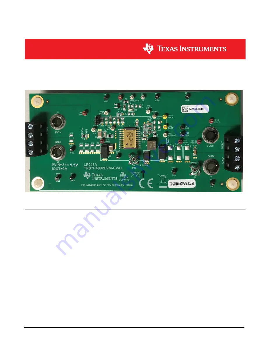
Figure 1-1. TPS7H4002EVM-CVAL
Table of Contents
1 TPS7H4002EVM-CVAL Overview
...........................................................................................................................................
3
2 TPS7H4002EVM-CVAL Default Configuration
......................................................................................................................
3
3 TPS7H4002EVM-CVAL Initial Setup
......................................................................................................................................
4
4 TPS7H4002EVM-CVAL Testing
..............................................................................................................................................
5
5 TPS7H4002EVM-CVAL EVM Schematic
..............................................................................................................................
15
6 TPS7H4002EVM-CVAL Bill of Materials (BOM)
..................................................................................................................
16
7 Board Layout
.........................................................................................................................................................................
18
List of Figures
Figure 1-1. TPS7H4002EVM-CVAL.............................................................................................................................................
1
Figure 4-1. Output Voltage Regulation........................................................................................................................................
5
Figure 4-2. Output Voltage Ripple VIN = 5 V, VOUT = 2.5 V, IOUT = 3 A...................................................................................
6
Figure 4-3. Output Soft Start Voltage, VIN = 5 V, VOUT = 2.5 V, IOUT = 3 A.............................................................................
7
Figure 4-4. Transient Response to Load Step 0 A to 3 A at 1 A/µs.............................................................................................
8
Figure 4-5. Transient Response to Load Step 3 A to 0 A at 1 A/µs.............................................................................................
9
Figure 4-6. Input Voltage Ripple, VIN = 5 V, VOUT = 2.5 V, IOUT = 3 A...................................................................................
10
Figure 4-7. EVM Modification to Measure Frequency Response...............................................................................................
11
Figure 4-8. Frequency Response Test Setup............................................................................................................................
12
Figure 4-9. Frequency Response IOUT = 3 A...........................................................................................................................
12
www.ti.com
Table of Contents
SLVUBI1 – MAY 2021
Submit Document Feedback
TPS7H4002EVM-CVAL Evaluation Module
1
Copyright © 2021 Texas Instruments Incorporated


