Texas Instruments TPS62869EVM-118 Скачать руководство пользователя страница 7

6 Software User Interface

6.1 Software Setup

A graphical user interface (GUI) is available from the 

TPS62869 tools and software page

, which allows simple 

and convenient programming of the device through the 

TI USB2ANY

 interface board. Alternatively, you can 

use any I

2

C-standardized programming tool or I

2

C host to configure the device. Mind the I²C pins specification, 

such as timing parameters and proper pullup resistors, specified in the 

TPS62869 2.4-V to 5.5-V Input, 6-A 

Synchronous Step-Down Converter Data Sheet

6.2 Interface Hardware Setup

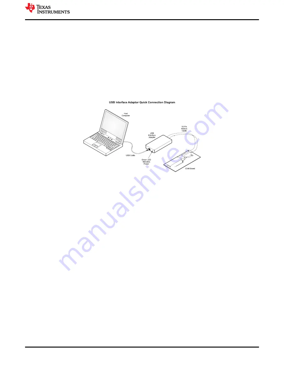
Connect the USB2ANY adapter to your PC using the supplied USB cable. Connect the EVM connector J3 to 
the USB2ANY adapter using the supplied 10-pin ribbon cable. The connectors on the ribbon cable are keyed to 
prevent incorrect installation. 

Figure 6-1

 shows a quick adapter connection overview.

Figure 6-1. Quick Connection Overview 

6.3 User Interface Operation

Upon start-up, the GUI automatically connects to the EVM. If not, click on the Connect button in the upper right 
corner of the GUI window. Ensure the I²C Slave Address is correct. The following sections give a short overview 
of the two main GUI screens.

6.3.1 Home Screen

The Home screen gives a short overview of the TPS62869 devices. To start evaluating the device, click on the 
Start button or on the Settings icons on the left side of the GUI window.

www.ti.com

Software User Interface

SLUUC88B – MARCH 2021 – REVISED NOVEMBER 2021

Submit Document Feedback

TPS62869EVM-118 Evaluation Module

7

Copyright © 2021 Texas Instruments Incorporated

Содержание TPS62869EVM-118

Страница 1: ...2 1 1 Performance Specification 2 1 2 Modifications 2 2 Setup 2 2 1 Input Output Connector Descriptions 2 2 2 Hardware Setup 2 3 TPS62869EVM 118 Test Results 3 4 Board Layout 3 5 Schematic and List of...

Страница 2: ...sure the output voltage at this point J2 Pin 5 and 6 GND Output return connection J3 Pin 5 VBUS The VBUS pin of this header is used to bias the SCL and SDA nodes of I C interface via a resistor J3 Pin...

Страница 3: ...his section provides the TPS62869EVM 118 board layout and illustrations in Figure 4 1 through Figure 4 7 The Gerbers are available on the EVM product page TPS62869EVM 118 Figure 4 1 Top Assembly Figur...

Страница 4: ...Figure 4 4 Signal Layer 2 Figure 4 5 Signal Layer 3 Board Layout www ti com 4 TPS62869EVM 118 Evaluation Module SLUUC88B MARCH 2021 REVISED NOVEMBER 2021 Submit Document Feedback Copyright 2021 Texas...

Страница 5: ...Signal Layer 4 Figure 4 7 Bottom Layer www ti com Board Layout SLUUC88B MARCH 2021 REVISED NOVEMBER 2021 Submit Document Feedback TPS62869EVM 118 Evaluation Module 5 Copyright 2021 Texas Instruments I...

Страница 6: ...2 Capacitor ceramic 22 F 6 3 V 20 X7R 0805 GRM21BZ70J226ME44L Murata C9 1 Capacitor Ceramic 47 F 6 3 V 20 X5R 0603 GRM188R60J476ME15D Murata C8 1 Capacitor tantalum 68 F 20 V 10 7343 T495D686K020ATE1...

Страница 7: ...ng the supplied 10 pin ribbon cable The connectors on the ribbon cable are keyed to prevent incorrect installation Figure 6 1 shows a quick adapter connection overview Figure 6 1 Quick Connection Over...

Страница 8: ...s Here single registers can be read or written to the device if applicable Refer to the register map in the TPS62869 2 4 V to 5 5 V Input 6 A Synchronous Step Down Converter Data Sheet for a detailed...

Страница 9: ...Revision B November 2021 Page Updated TPS628692 to TPS628682 1 Updated title from Setup to Hardware Setup 2 Changes from Revision May 2021 to Revision A March 2021 Page Updated TPS62869EVM 118 Schemat...

Страница 10: ...ther than TI b the nonconformity resulted from User s design specifications or instructions for such EVMs or improper system design or c User has not paid on time Testing and other quality control tec...

Страница 11: ...These limits are designed to provide reasonable protection against harmful interference in a residential installation This equipment generates uses and can radiate radio frequency energy and if not in...

Страница 12: ...instructions set forth by Radio Law of Japan which includes but is not limited to the instructions below with respect to EVMs which for the avoidance of doubt are stated strictly for convenience and s...

Страница 13: ...any interfaces electronic and or mechanical between the EVM and any human body are designed with suitable isolation and means to safely limit accessible leakage currents to minimize the risk of electr...

Страница 14: ...R DAMAGES ARE CLAIMED THE EXISTENCE OF MORE THAN ONE CLAIM SHALL NOT ENLARGE OR EXTEND THIS LIMIT 9 Return Policy Except as otherwise provided TI does not offer any refunds returns or exchanges Furthe...

Страница 15: ...change without notice TI grants you permission to use these resources only for development of an application that uses the TI products described in the resource Other reproduction and display of thes...

Отзывы: