


10.2 General Settings
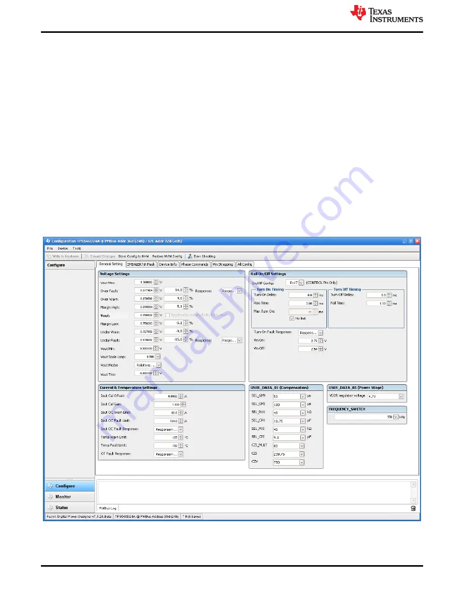
General Settings
that can be used to configure the following:
• V
OUT
settings, power good limits, and margin voltages
• OC Fault, OC Warn, and Fault response
• OT Fault, OT Warn (Die Temperature), and Fault response
• VIN on and off UVLO
• On/Off Config
• Soft Start (Output rise time), other Turn On Timing, and Turn Off Timing
• Switching frequency
• Compensation
After clicking
Write to Hardware
to make changes to one or more configurable parameters, the changes can
be committed to nonvolatile memory by clicking
Store Config to NVM
. This action prompts a pop-up, and
if confirmed, the changes are committed to nonvolatile memory to store all the modifications in non-volatile
memory.
Both the loop controller device and the loop follower device are tied to same bus interface. In a two-phase
stacking system, the controller device will receive and respond to all PMBus communication and follower devices
do not need to be connected to the PMBus. If the controller receives commands that require updates to the
PMBus registers of the follower, the controller will relay these commands to the followers. All commands on this
tab are for PHASE = 0xFF.
Figure 10-2. General Settings
Using the Fusion GUI
32
TPS546B24A 2-Phase SWIFT™ Step-Down Converter Evaluation Module
User's Guide
SLUUC48A – FEBRUARY 2020 – REVISED FEBRUARY 2022
Copyright © 2022 Texas Instruments Incorporated