park_D
park_Q
clarke_d
clarke_q
Valpha
Vbeta
Tb
Ta
Tc
Ipark_d
Ipark_Q
Ipark_D
Theta
Ipark_q
Mfunc_c1
Mfunc_c2
Mfunc_c3
PWM1A
PWM
DRV
MACRO
PWM1B
PWM2A
PWM2B
PWM3A
PWM3B
EV
HW
3-Phase
Inverter
PMSM
Motor
ADC
DRV
EV
HW
Ia
Vdc
Ib
AdcRslt0
AdcRslt1
clarke_a
clarke_b
park_d
park_q
PARK
MACRO
CLARKE
MACRO
SVGEN
DQ
MACRO
IPARK
MACRO
theta
watch window
Speed_Ref
PID
MACRO
Iq Reg.
IdRef (=0)
PID
MACRO
Id Reg.
QEP
DRV
EV
HW
QEPA
QEPB
Index
Elec
Theta
Direction
Speed
Speed Rpm
SPEED_FR
MACRO
u_out_q
u_out_d
i_ref_d
i_ref_q
PID
MACRO
Iq Reg.
spd_fdb
/
/
/
,
(
2
)
/
,
(
/
)
pu
base
pu
base
pu
base
base
base
pu
base
base
base
base
I
I I
V
V V
w
w w
w
f
V
w
p
=
=
=
=
Y
= Y
Y
Y
=
www.ti.com
Software Tools
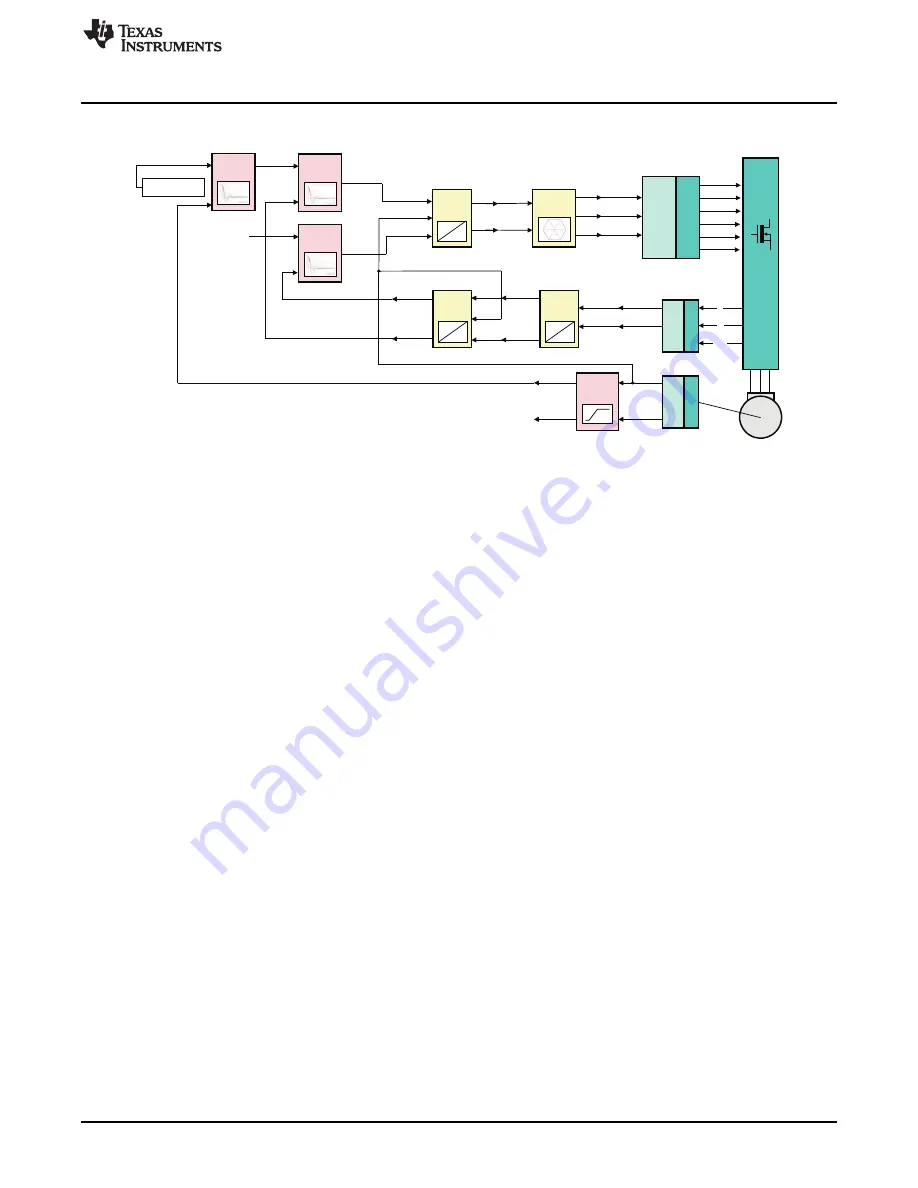
Figure 17. Build Level IV - Closed Speed Loop Test / FOC
2.5
PU System Model and Base Values
In electrical engineering, a per-unit system is the expression of system quantities as fractions of a defined
base unit quantity. Calculations are simplified because quantities expressed as per-unit (between -1 and
+1) are the same regardless of the voltage, current etc level. Advantages of using the pu system for motor
control applications include:
•
Once the base values are initialized in the code, the code will handle the rest and the parameter
dependency will be minimized.
•
Migrating to a new custom design system will be as easy as modifying the base values.
•
For fixed point devices, pu system allows the user to reduce the amplitude of the variables in order to
get a fractional part with a maximum precision.
Conversion of per-unit quantities to volts, ohms, or amperes requires knowledge of the base that the
per-unit quantities were referenced to. In the TI DMC systems, the base values are selected as the
maximum measurable quantity of the peak of phase voltage, current etc. by the ADC. This is directly
related to the current and voltage sensing circuits and the voltage dividers used to down-scale the actual
voltage or current quantities to ADC input voltage range, which is typically 3 to 3.3V. Later, the measured
voltage by ADCs will be converted to put quantity in the code. The calculation of the pu values can be
formulated as:
The selection of the base quantities is relative and can be any appropriate value as long as it is consistent
within the whole system. For instance, assuming that the peak of the maximum measurable phase current
is 20A on a DMC kit, the base current value can be selected as 20 where ±1pu represents ±20A in the
code.
21
SPRUGI6 – September 2010
TMS320C2000 Motor Control Primer
Submit Documentation Feedback
Copyright © 2010, Texas Instruments Incorporated


